
1. Introduction
This manual provides detailed instructions for the installation, operation, and maintenance of the Ransanx Stepper Motor Controller, model ZK-SMC05. This controller is designed for precise control of Nema 17, Nema 23, and Nema 34 stepper motors, offering a wide range of motion modes and industrial connectivity options. Please read this manual thoroughly before use to ensure proper and safe operation.
2. Safety Precautions
- Power Supply: Ensure the power supply voltage is within the specified DC 12-24V range. Incorrect voltage can damage the device.
- Wiring: All wiring should be performed by qualified personnel. Ensure power is disconnected before making any connections.
- Environment: Operate the controller within the specified operating temperature range of -5°C to +60°C (non-condensing). Avoid exposure to moisture, dust, and corrosive gases.
- Grounding: Proper grounding is essential for safety and to prevent electromagnetic interference.
- Emergency Stop: Always incorporate an accessible emergency stop mechanism in your system.
3. Package Contents
Verify that all items are present in the package:
- 1 x Ransanx Stepper Motor Controller (Main Unit)
- 1 x Quick Start Guide
- Terminal Blocks & Connection Cables

Figure 3.1: Included Components
4. Product Features
- Intuitive 1.8" Color Screen: Real-time display of speed, pulse, and other parameters. Easy parameter setting via rotary encoder.
- Industrial Modbus Connectivity: Supports Modbus protocol via Serial/RS-485 for reliable integration with PLC and PC control systems.
- Wide Motor Compatibility: Universal pulse speed and direction control for Nema 17, Nema 23, and Nema 34 stepper motors (DC 12-24V).
- High Precision & Versatility: Features 1Hz–200kHz pulse frequency and 20 built-in motion modes for precise control.
- Robust & Expandable I/O: Equipped with 4 limit switch inputs and 3 expansion key interfaces for flexible custom control.
5. Specifications
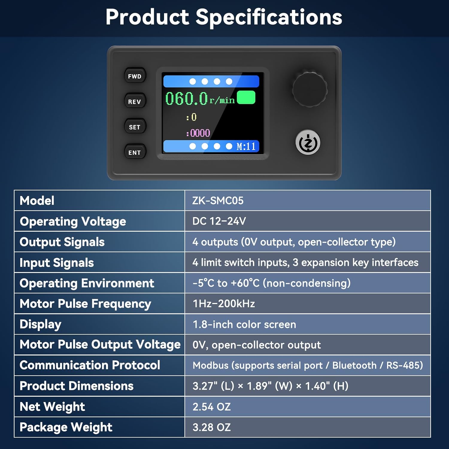
Figure 5.1: Product Specifications Overview
| Parameter | Value |
|---|---|
| Model | ZK-SMC05 |
| Operating Voltage | DC 12-24V |
| Output Signals | 4 outputs (0V output, open-collector type) |
| Input Signals | 4 limit switch inputs, 3 expansion key interfaces |
| Operating Environment | -5°C to +60°C (non-condensing) |
| Motor Pulse Frequency | 1Hz-200kHz |
| Display | 1.8-inch color screen |
| Motor Pulse Output Voltage | 0V, open-collector output |
| Communication Protocol | Modbus (supports serial port / Bluetooth / RS-485) |
| Product Dimensions | 3.27" (L) × 1.89" (W) × 1.40" (H) |
| Net Weight | 2.54 OZ |
| Package Weight | 3.28 OZ |
6. Hardware Overview
6.1 Front Panel and Display

Figure 6.1: Main Interface Display and Operation
The front panel features a 1.8-inch color screen for real-time data display and user interaction. Key controls include:
- FWD (Forward): Initiates forward rotation.
- REV (Reverse): Initiates reverse rotation.
- SET: Enters parameter setting mode or navigates menus.
- ENT (Enter): Confirms selections or exits menus.
- Rotary Knob: Adjusts parameter values and navigates menus.
- Start/Stop Button: Toggles motor operation.
6.2 Back Interface and I/O Ports

Figure 6.2: Back Interface Schematic Diagram
The back interface provides various connection points:
- Power Supply (DC 12-24V): Connect the main power input.
- Limit Switch Inputs (X1-X4): For connecting external limit switches.
- Expansion Button Ports: For connecting additional control buttons.
- Communication Interface: For Modbus RS485 connection.
- Stepper/Servo Motor Drive Outputs (PUL, DIR, EN): Connect to your motor driver.
- Outputs (O1-O4): General purpose outputs.
7. Wiring and Connections
Proper wiring is crucial for the functionality and safety of the controller. Refer to the diagrams below for correct connections.
7.1 Motor Drive Wiring Diagram

Figure 7.1: Motor Drive Wiring Diagram
Connect the controller to your stepper motor driver using the PUL (Pulse), DIR (Direction), and EN (Enable) signals. Ensure the power supply for both the controller and the motor driver are correctly connected and grounded.
7.2 Power Supply Connection
Connect a DC 12-24V power source to the designated power input terminals on the back of the controller. Observe polarity: positive to '+' and negative to '-'.
7.3 Limit Switch and Expansion Key Connections
Connect external limit switches to inputs X1-X4 as required by your application. Expansion keys can be connected to their respective ports for additional control functions.
8. Basic Operation
8.1 Powering On
After all connections are securely made, apply power to the controller. The 1.8-inch color screen will illuminate, displaying the main operating interface.
8.2 Navigating the Display
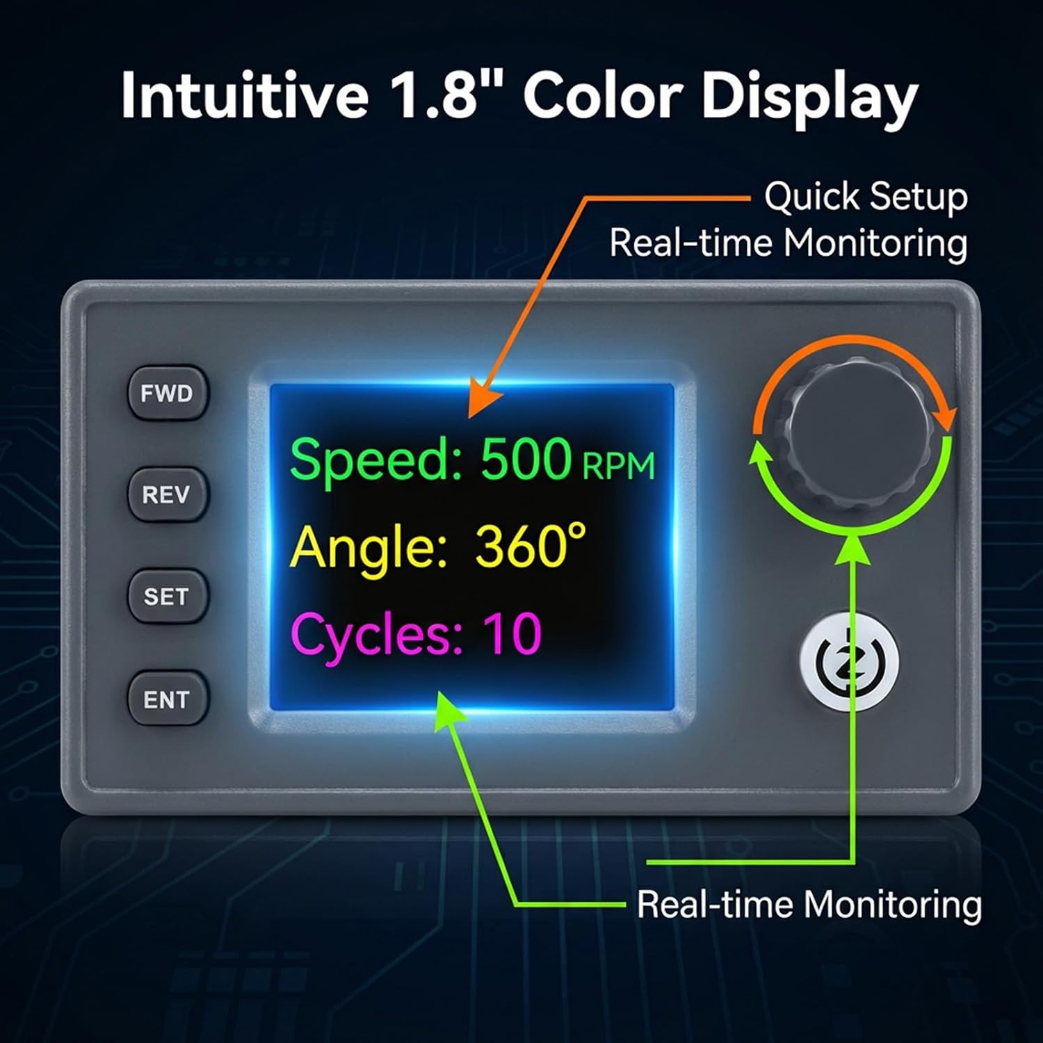
Figure 8.1: Intuitive Color Display
The display shows real-time operational data such as speed (RPM), pulse count, and current motion mode. Use the rotary knob to scroll through options and the SET/ENT buttons to select or confirm.
8.3 Starting and Stopping Motor Movement
- Press the FWD button to initiate forward rotation.
- Press the REV button to initiate reverse rotation.
- Press the Start/Stop button to pause or resume motor movement.
9. Operating Modes
The controller features 20 versatile built-in motion modes, allowing for various complex tasks without external programming. These modes cover a wide array of industrial and DIY project requirements, from simple forward/reverse movements to multi-segment automated sequences.

Figure 9.1: 20 Versatile Motion Modes
To select a mode, navigate to the 'Mode' setting using the SET button and rotary knob, then confirm with ENT. Refer to the Quick Start Guide for a detailed description of each mode and its parameters.
10. Parameter Settings
The controller allows adjustment of various parameters to fine-tune motor behavior. These include speed, pulse count, acceleration/deceleration, and delay times.
- Press the SET button to enter the parameter setting menu.
- Use the Rotary Knob to scroll through the available parameters.
- Press ENT to select a parameter for editing.
- Turn the Rotary Knob to adjust the value of the selected parameter.
- Press ENT again to confirm the new value.
- Press SET to exit the parameter setting menu.
11. Modbus Communication
The ZK-SMC05 supports Modbus protocol via its RS-485 interface, enabling integration with industrial control systems like PLCs and PCs. This allows for remote control and monitoring of the stepper motor controller.
- Connection: Connect the RS-485 A and B terminals of the controller to your Modbus master device.
- Protocol: The controller operates as a Modbus slave device. Refer to the detailed Modbus communication protocol document (available separately or in the full manual) for register addresses and command structures.
- Baud Rate: Ensure the baud rate and other communication parameters are matched between the controller and the Modbus master.
12. Troubleshooting
- Controller does not power on:
- Check power supply voltage (DC 12-24V).
- Verify power connections for correct polarity and secure contact.
- Motor does not move:
- Ensure motor driver is powered and enabled.
- Check PUL, DIR, EN connections between controller and driver.
- Verify motor parameters (speed, pulse count) are set correctly and not zero.
- Check for active limit switch inputs that might be preventing movement.
- Incorrect motor direction:
- Reverse the DIR signal connection or adjust the direction setting in the controller.
- Display shows error:
- Refer to the Quick Start Guide for specific error codes and their meanings.
- Power cycle the device.
13. Maintenance
The Ransanx Stepper Motor Controller is designed for reliable operation with minimal maintenance.
- Cleaning: Keep the device clean and free from dust. Use a soft, dry cloth for cleaning. Do not use liquid cleaners or solvents.
- Inspection: Periodically check all wiring connections for tightness and signs of wear or damage.
- Storage: If storing the controller for an extended period, ensure it is kept in a dry, cool environment, away from direct sunlight and extreme temperatures.
14. Customer Support
For technical assistance, warranty information, or further inquiries, please contact Ransanx customer support through your purchase platform or the official Ransanx website.