
1. Introduction
This manual provides detailed instructions for the installation, operation, and maintenance of the STEPPERONLINE CL86Y-V20 Closed Loop Stepper Motor Kit. This kit is designed for precision motion control applications, such as 3D printers, CNC machines, carving machines, dispensers, and other automation systems.
The kit includes a Nema 34 closed-loop stepper motor (Model: 34HS59-6004D-E1K-1M5) and a high-performance closed-loop stepper driver (Model: CL86Y-V20).
2. Package Contents
Verify that all components listed below are included in your package:
- 1 x CL86Y-V20 Y Series Closed Loop Stepper Driver V2.0 (0-8.5A, 20-80VAC/30-110VDC)
- 1 x 34HS59-6004D-E1K-1M5 S Series Nema 34 Closed Loop Stepper Motor (12.00Nm/1699.34oz.in) with 1000PPR Encoder
- 1 x CABLE-PC-2 RS232 Debugging Cable (1.5 meters)
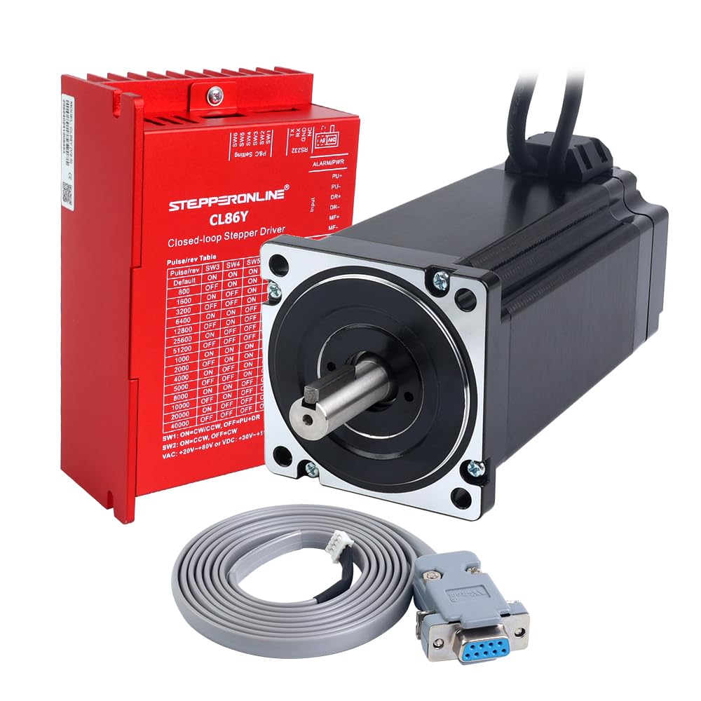
Image 1: Overview of the STEPPERONLINE CL86Y-V20 Closed Loop Stepper Motor Kit. This image displays the main components included in the kit: the Nema 34 closed-loop stepper motor, the CL86Y-V20 stepper driver, and the RS232 debugging cable.
3. Safety Information
Please read and understand all safety instructions before installing or operating this product. Failure to follow these instructions may result in electric shock, fire, serious injury, or property damage.
- Electrical Safety: Ensure all power is disconnected before making any electrical connections. Work with qualified personnel when dealing with high voltage.
- Grounding: Properly ground the equipment to prevent electrical hazards.
- Ventilation: Ensure adequate ventilation for the driver to prevent overheating.
- Environmental Conditions: Do not expose the components to moisture, dust, corrosive gases, or extreme temperatures.
- Moving Parts: Keep hands and loose clothing away from moving motor parts during operation.
4. Setup and Installation
4.1. Component Identification

Image 2: Nema 34 Closed Loop Stepper Motor (Model: 34HS59-6004D-E1K-1M5). This image shows the physical appearance of the stepper motor, highlighting its robust construction and shaft.

Image 3: CL86Y-V20 Closed Loop Stepper Driver. This image displays the stepper driver, showing its various connection terminals and DIP switches for configuration.

Image 4: RS232 Debugging Cable. This image shows the RS232 cable used for connecting the driver to a computer for debugging and advanced configuration.
4.2. Wiring Connections
Proper wiring is critical for the correct operation of the closed-loop stepper system. Refer to the diagrams and tables below for motor, encoder, and power connections.
4.2.1. Motor Wiring
Connect the motor phases to the driver's A+, A-, B+, B- terminals as indicated:
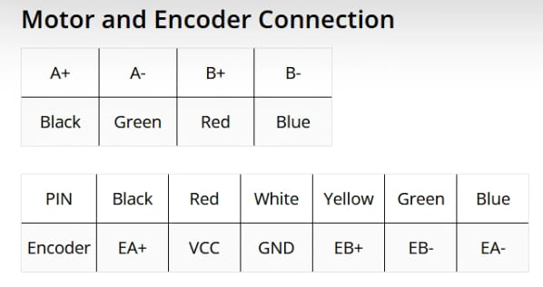
Image 5: Motor and Encoder Connection Diagram. This diagram illustrates the wiring connections for both the motor phases (A+, A-, B+, B-) and the encoder signals (EA+, VCC, GND, EB+, EB-, EA-), showing corresponding wire colors.
| Driver Terminal | Motor Wire Color |
|---|---|
| A+ | Black |
| A- | Green |
| B+ | Red |
| B- | Blue |
4.2.2. Encoder Wiring
Connect the encoder wires to the driver's encoder input terminals:
| Driver Terminal | Encoder Wire Color |
|---|---|
| EA+ | Black |
| VCC | Red |
| GND | White |
| EB+ | Yellow |
| EB- | Green |
| EA- | Blue |
4.2.3. Power Supply Connection
Connect the power supply to the driver's AC/DC input terminals. The driver supports an input voltage range of 20-80VAC or 30-110VDC. Ensure the power supply is stable and within the specified range.
4.2.4. Control Signal Connection
Connect your controller's pulse (PU), direction (DR), and enable (MF) signals to the corresponding input terminals on the driver. The logic signal current is typically 10mA (7-16mA).
4.3. Driver Configuration (DIP Switches)
The CL86Y-V20 driver features DIP switches for setting the microstep resolution (Pulse/rev) and direction control. Refer to the image below for switch locations and settings.
Image 6: CL86Y-V20 Closed Loop Stepper Driver with DIP Switch Table. This image clearly shows the DIP switches on the driver and a printed table indicating how to set them for different pulse/revolution values (microstep resolutions) and direction control.
Pulse/rev Table: Use SW3, SW4, SW5, SW6 to set the desired microstep resolution. The default setting is 800 pulses/revolution.
- SW1: ON=CW/CCW, OFF=PU+DR (Pulse/Direction mode)
- SW2: ON=CCW, OFF=CW (Direction setting)
Note: For detailed microstep settings, refer to the table printed on the driver or the full product datasheet.
4.4. Control Signal Voltage Selector
The CL86Y-V20 driver has a 5V/24V selector on the top for the control signal voltage. The factory setting is 24V. Adjust this selector to match your controller's signal voltage (5V or 24V) to ensure proper communication.

Image 7: Stepper Driver Version Comparison (CL86Y V1.0 vs V2.0). This table compares key features and differences between the CL86Y V1.0 and V2.0 drivers, including control signal voltage, digital output, performance, and debug port type. The V2.0 driver features a 5V/24V selector and RS232 debug port.
5. Operating Instructions
Once the motor and driver are correctly wired and configured, you can begin operation.
- Power On: Apply power to the driver. The status LED should indicate normal operation.
- Send Commands: Use your CNC controller or motion control software to send pulse and direction signals to the driver.
- Closed-Loop Operation: The closed-loop system continuously monitors the motor's position via the encoder and corrects any position errors, ensuring high precision and preventing step loss.
- Monitoring: Observe the motor's movement and listen for any unusual noises. If an alarm occurs, refer to the Troubleshooting section.
6. Maintenance
The STEPPERONLINE Closed Loop Stepper Motor Kit is designed for reliable operation with minimal maintenance. However, periodic checks can help ensure longevity and optimal performance.
- Cleaning: Keep the motor and driver free from dust and debris. Use a soft, dry cloth or compressed air for cleaning.
- Connections: Periodically check all wiring connections to ensure they are secure and free from corrosion.
- Temperature: Ensure the operating temperature of the driver and motor remains within specified limits. Adequate ventilation is crucial.
- Physical Inspection: Inspect the motor shaft and mounting for any signs of wear or damage.
7. Troubleshooting
This section provides solutions to common issues you might encounter.
| Problem | Possible Cause | Solution |
|---|---|---|
| Motor does not move or moves erratically. | Incorrect wiring; insufficient power supply; incorrect DIP switch settings; control signals not present. | Verify all wiring connections (motor, encoder, power, control signals). Check power supply voltage. Confirm DIP switch settings match desired microstep resolution. Ensure controller is sending valid pulse/direction signals. |
| Motor loses steps or stalls. | Overload; motor current too low; excessive acceleration/deceleration; mechanical binding. | Reduce load on the motor. Check driver current settings (if adjustable via software). Adjust acceleration/deceleration parameters in your controller. Inspect mechanical system for obstructions. |
| Driver alarm LED is on. | Over-voltage, under-voltage, over-current, encoder error, position error. | Check power supply voltage. Verify motor and encoder connections. Reduce load. Power cycle the driver. If the issue persists, contact support. |
| Motor runs hot. | Excessive current; poor heat dissipation; continuous high load. | Ensure adequate ventilation around the motor and driver. Check if the motor current setting is appropriate for the application. Reduce load if possible. |
For further assistance, please contact STEPPERONLINE technical support.
8. Specifications
8.1. Motor Specifications (Model: 34HS59-6004D-E1K-1M5)
- Manufacturer Part Number: 34HS59-6004D-E1K-1M5
- Motor Type: Bipolar Stepper
- Step Angle: 1.8 degrees
- Holding Torque: 12.00Nm (1699.34oz.in)
- Rated Current/phase: 6.0A
- Phase Resistance: 0.59ohms ± 10%
- Inductance: 4.8mH ± 20% (1KHz)
- Insulation Class: B 130°C [266°F]
- Frame Size: 86 x 86mm
- Body Length: 174mm
- Shaft Diameter: Φ14mm
- Shaft Length: 37mm
- D-Cut Length: 25mm
- Cable Length: 1500mm
- Encoder Type: Optical Incremental
- Encoder Resolution: 1000PPR (4000CPR)
- Output Signal Channels: 2 channels
- Encoder Supply Voltage: Min 4V, Max 5V
- Encoder Output Current: 100mA
- Encoder Output High Voltage: 5V
- Encoder Output Low Voltage: 4.5V
- Encoder Output Frequency Max: 60kHz
8.2. Driver Specifications (Model: CL86Y-V20)
- Output Peak Current: 0~8.5A (0~6 RMS)
- Input Voltage: 20~80VAC / 30~110VDC (Typical 48/60VDC)
- Logic Signal Current: 7~16mA (Typical 10mA)
- Pulse Input Frequency: 0~200kHz
- Pulse Width: 2.5µS
- Isolation Resistance: 500MΩ
- Microstep Resolutions: 800 - 40000 (via DIP switches)
- Control Signal Voltage: 5V/24V selectable
- Debug Port: RS232
9. Warranty and Support
For warranty information and technical support, please contact STEPPERONLINE directly through their official website or the retailer where the product was purchased. Ensure you have your product model number and purchase details available when contacting support.
Manufacturer: OMC Corporation Limited
Brand: STEPPERONLINE
For additional resources and product information, visit the STEPPERONLINE Store on Amazon.


