
1. Introduction
This manual provides detailed instructions for the Shutao 2 Channel 18650 Battery Capacity Tester. This device is designed for comprehensive analysis of 18650 lithium batteries, offering independent charging, discharging, and capacity testing on two channels. It also includes internal resistance measurement capabilities, making it an essential tool for battery management and evaluation.
Key features include:
- Independent Dual Channels: Simultaneously test two batteries without interference.
- Automatic Operation: Supports fully automatic charge and discharge cycles (1-9 cycles adjustable).
- Internal Resistance Test: Utilizes the DC two-wire method for reference internal resistance values.
- Safety Protections: Overheating protection and automatic power-off with settings saved.
- Flexible Discharge Voltage: 11 selectable stop-discharge voltage levels (2.5V to 3.5V).
- Dual Type-C Power Input: Provides flexible power supply options.
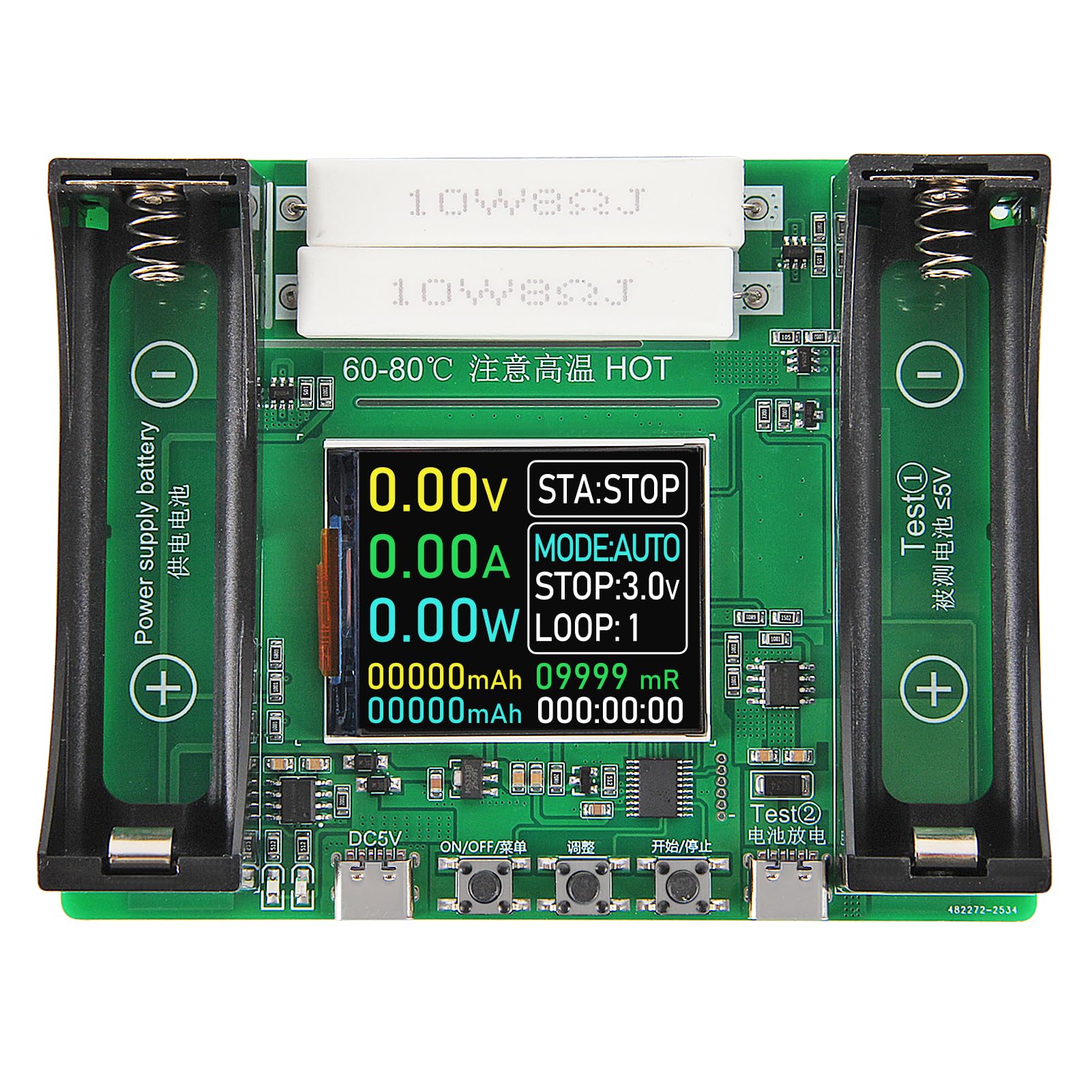
Figure 1: Shutao 2 Channel 18650 Battery Capacity Tester overview.
2. Product Components and Interface
Familiarize yourself with the components and interface of the battery capacity tester before operation.

Figure 2: Labeled diagram of the tester's components.
- Power Supply Battery Compartment: Slot for the device's power supply battery.
- Charging Monitoring Indicator: Blue and red indicator light for the power supply battery's charging status. This does not relate to the test channels (8/9).
- Type-C 5V Power Supply Interface: Primary power input for the device.
- "ON/OFF/Menu" Button: Used for powering on/off and navigating menu options.
- "Adjust" Button: Used to cycle through modes and adjust settings.
- "Start/Stop" Button: Initiates or terminates a test cycle.
- Test ② Type-C External Discharge Interface: Secondary Type-C port for external discharge testing.
- Test ① Charging and Discharging 18650 Battery Compartment: Main slot for testing 18650 batteries.
- 1.77 inch Display Screen: Shows real-time test data and settings.
- 10W8ΩJ Discharge Cement Resistance x2: Resistors used for discharge load.
Note: Test ① (8) and Test ② (7) cannot be tested at the same time.

Figure 3: Display interface introduction.
- Real Time Voltage: Displays the current voltage of the battery under test.
- Real Time Current: Shows the current flowing during charge or discharge.
- Real Time Power: Indicates the instantaneous power.
- Cumulative Capacity: Total capacity measured (mAh).
- Accumulated Energy: Total energy measured (mWh).
- Status Indicator: Shows the current operational status (e.g., STA:STOP, STA:CHG, STA:DIS).
- Work Pattern: Indicates the current mode (e.g., MODE:AUTO, MODE:CHG, MODE:DIS).
- Stop Discharge Voltage: The set voltage at which discharge will stop.
- Cycles: Number of completed charge/discharge cycles in AUTO mode.
- Battery Internal Resistance: Reference internal resistance value (mR).
- Cumulative Time: Total time elapsed for the current test.
3. Setup
Follow these steps to set up your battery capacity tester for first use:
- Power Connection: Connect the device to a 5V DC power source using a Type-C cable (not included) via the Type-C 5V Power Supply Interface (3).
- Optional Power Supply Battery: For portable use or to power the device itself, insert a compatible battery into the Power Supply Battery Compartment (1). Note that this battery is for device power only and not for testing.
- Battery Insertion for Test:
- For 18650 batteries, insert the battery into the Test ① Charging and Discharging 18650 Battery Compartment (8), ensuring correct polarity.
- For external batteries or devices, connect them to the Test ② Type-C External Discharge Interface (7).
- Power On: Press the "ON/OFF/Menu" button (4) to power on the device. The display screen (9) will illuminate.
- Stabilization: After installing a battery, wait a few seconds for the voltage and internal resistance readings to stabilize on the display before proceeding with tests.
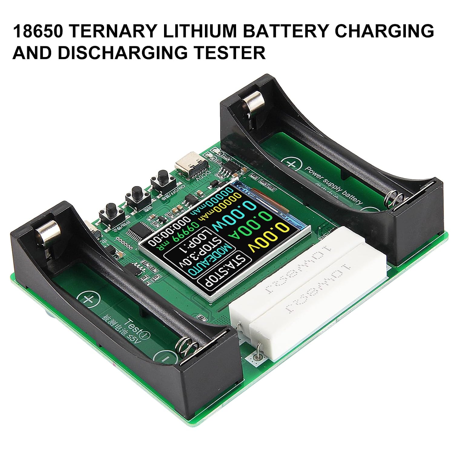
Figure 4: Battery inserted into the test compartment.
4. Operating Instructions
The tester offers various modes for battery analysis. Use the "ON/OFF/Menu" (4), "Adjust" (5), and "Start/Stop" (6) buttons to navigate and control operations.
4.1. Mode Selection
Press the "Adjust" button (5) to cycle through the available modes:
- AUTO Mode: Performs a full charge-discharge cycle (or multiple cycles) to measure capacity.
- CHARGE Mode: Charges the battery to 4.2V.
- DISCHARGE Mode: Discharges the battery to a user-selected stop voltage.
4.2. Starting and Stopping Tests
Once a mode is selected and settings are configured (if applicable), press the "Start/Stop" button (6) to begin the test. Press it again to stop the test at any time.
When a test is stopped, a long press of the "Start/Stop" button (6) will reset the on-screen data.
4.3. AUTO Mode Operation
- Insert the battery into the Test ① compartment (8) or connect to Test ② (7).
- Press "Adjust" (5) until "MODE:AUTO" is displayed.
- Use the "ON/OFF/Menu" button (4) to adjust the number of cycles (1-9) and the stop-discharge voltage (2.5V to 3.5V).
- Press "Start/Stop" (6) to begin. The tester will automatically charge, discharge, and recharge the battery for the set number of cycles, displaying cumulative capacity and energy.
- The test will automatically stop when all cycles are completed.
4.4. CHARGE Mode Operation
- Insert the battery into the Test ① compartment (8) or connect to Test ② (7).
- Press "Adjust" (5) until "MODE:CHG" is displayed.
- Press "Start/Stop" (6) to begin charging. The charging voltage is fixed at 4.2V.
- Charging automatically stops when the battery is full.
4.5. DISCHARGE Mode Operation
- Insert the battery into the Test ① compartment (8) or connect to Test ② (7).
- Press "Adjust" (5) until "MODE:DIS" is displayed.
- Use the "ON/OFF/Menu" button (4) to select the desired stop-discharge voltage (2.5V to 3.5V).
- Press "Start/Stop" (6) to begin discharging. The discharge current is fixed at approximately 1A.
- Discharging automatically stops when the battery reaches the set stop voltage.
4.6. Internal Resistance Measurement
The tester provides a reference internal resistance value (mR) using the DC two-wire method. For the most accurate reading, measure when the battery is fully charged. The internal resistance is displayed on the screen (10).
5. Maintenance
- Cleaning: Keep the device clean and free from dust and debris. Use a soft, dry cloth for cleaning.
- Storage: Store the tester in a cool, dry place away from direct sunlight and extreme temperatures.
- Handling: Handle the device with care to avoid physical damage.
- Heat Management: The discharge load resistors (10) can get hot during operation. Ensure adequate ventilation and avoid touching them during or immediately after a test. The device includes active cooling and high-temperature protection.
6. Troubleshooting
- Inaccurate Internal Resistance Readings: If internal resistance readings appear high, especially at low battery voltages, try reinstalling the battery or measuring when the battery is fully charged for a more accurate result.
- Device Not Powering On: Ensure the Type-C power cable is securely connected to a 5V DC power source, or that a charged battery is inserted into the Power Supply Battery Compartment (1).
- Test Not Starting: Verify that a battery is properly inserted with correct polarity and that a test mode has been selected. Press the "Start/Stop" button (6) firmly.
- No Display: Check power connection. If the device is powered but the screen is blank, try pressing the "ON/OFF/Menu" button (4).
- Compatibility Issues: This tester is not compatible with LiFePO4 batteries. Ensure you are testing compatible lithium-ion batteries (e.g., 18650 flat-top).
- Confusing Channel Operation: Remember that Test ① (18650 compartment) and Test ② (external Type-C) cannot be used simultaneously for testing.
7. Specifications
| Feature | Specification |
|---|---|
| Model | 2 Channel 18650 Battery Capacity Tester |
| Input Voltage | DC 5V (via Type-C) |
| Test Channels | 2 (18650 compartment, external Type-C) - not simultaneous |
| Discharge Current | Fixed at ~1A (non-adjustable) |
| Charging Voltage | Fixed at 4.2V |
| Stop Discharge Voltage | Adjustable (2.5V to 3.5V, 11 levels) |
| Automatic Cycles | 1-9 cycles adjustable |
| Display | 1.77 inch LCD |
| Supported Battery Types | Flat-top 18650 lithium batteries (not LiFePO4) |
| Safety Features | Overheating protection, automatic power-off |
| Dimensions | Approximately 108mm x 85mm (4.25in x 3.34in) |

Figure 5: Product dimensions.
8. Warranty and Support
This product is manufactured by Shutao. For specific warranty information, please refer to the documentation provided with your purchase or contact the seller directly. General support inquiries can often be resolved by reviewing this manual or contacting the retailer where the product was purchased.
Please retain your proof of purchase for any warranty claims.