
1. Introduction
This manual provides comprehensive instructions for the installation, operation, and maintenance of your SINOTIMER 12VDC 2-Channel Programmable Digital Timer Switch, Model TM922. This device is designed to automatically control the ON/OFF states of various electrical equipment at preset times, offering convenience and energy efficiency. Please read this manual thoroughly before installation and use to ensure proper function and safety.
2. Safety Information
- Electrical Hazard: Installation should only be performed by qualified personnel. Ensure power is disconnected at the circuit breaker before any wiring.
- Voltage Compatibility: This device operates on 12VDC input. Do not connect to higher voltage AC power supplies.
- Load Capacity: Do not exceed the maximum load rating of 16A per relay output. Overloading can cause damage to the device and create a fire hazard.
- Proper Wiring: Ensure all wire connections are secure and correctly matched to the terminals. Loose connections can lead to overheating or malfunction.
- Indoor Use Only: This timer switch is designed for indoor use in dry environments. Avoid exposure to moisture, extreme temperatures, or corrosive substances.
3. Product Features
- Input operating voltage: 12VDC.
- 8 ON/OFF programs per day, 15 combinations per week.
- Two independent relay outputs (C1 and C2) for controlling two separate devices simultaneously.
- Large LCD display with blue backlight for easy readability in low light conditions.
- Bi-color LED indicators for each relay channel to show operating status.
- Accurate-to-the-second control, with cycles from one second to 168 hours.
- Replaceable battery for long life usage, preserving programs during power failures.
- DIN standard 35mm mounted design for easy installation in DB boxes.
4. Product Overview


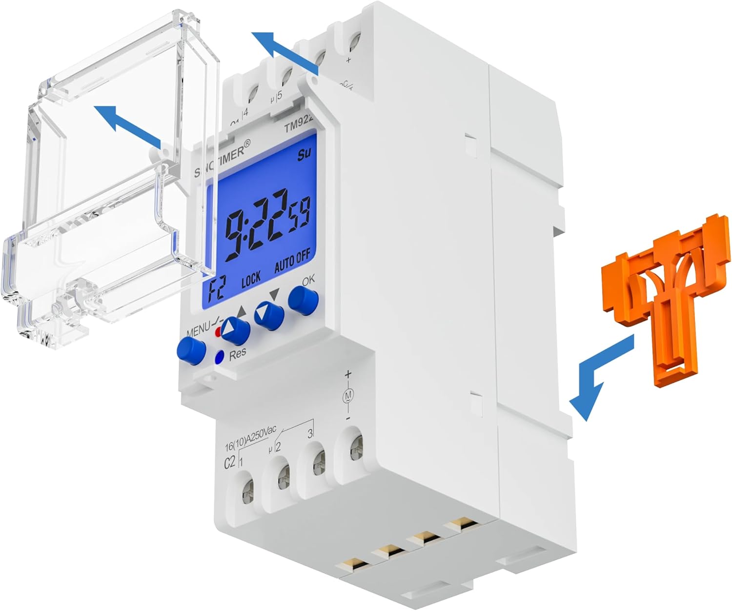

5. Specifications
| Attribute | Value |
|---|---|
| Brand | SINOTIMER |
| Model | TM922 |
| Input Operating Voltage | 12VDC |
| Output Relays | 2 Independent, 16A |
| Material | Metal (internal components), Plastic (housing) |
| Item Weight | 5.8 ounces (0.36 Pounds) |
| Product Dimensions | 1.42 x 2.68 x 3.54 inches |
| Number of Settings | Up to 8 ON/OFF programs per day, 15 combinations per week |
| Control Range | 1 second to 168 hours |
| Display | LCD with Blue Backlight |
6. Installation
The SINOTIMER TM922 is designed for DIN rail mounting. Ensure all power is disconnected before proceeding with installation.
- Mounting: Securely attach the timer switch to a standard 35mm DIN rail within your electrical enclosure. The integrated orange clip on the back facilitates easy mounting and removal.
- Wiring (12VDC Input): Refer to the terminal diagram on the device.
- Connect the 12VDC power supply to terminals 1 (positive) and 2 (negative).
- Relay 1 (C1): Terminals 4 and 5 are the normally open (NO) contacts for the first relay. Terminal 6 is the common (COM) contact. Connect your first load to these terminals as required (e.g., power to 6, load to 4 or 5).
- Relay 2 (C2): Terminals 1 and 2 are the normally open (NO) contacts for the second relay. Terminal 3 is the common (COM) contact. Connect your second load to these terminals as required (e.g., power to 3, load to 1 or 2).
- Secure Connections: Ensure all wires are stripped to the appropriate length and securely fastened into their respective screw terminals. Avoid loose connections.
- Close Cover: Once wiring is complete, close the protective cover over the buttons and terminals.
7. Operation & Programming
The TM922 timer switch allows for precise control over your connected devices. The blue-backlit LCD provides clear information, and the intuitive button layout simplifies programming.
7.1. Initial Setup & Reset
- Upon first power-up or after a long period without power, the display may be blank. Press the 'Res' (Reset) button with a pointed object (like a pen tip) to initialize the device. The display will show '00:00' and 'MO' (Monday).
7.2. Setting Current Time
- Press the 'MENU' button once to enter time setting mode. The hour digit will flash.
- Use the 'H+' button to adjust the hour.
- Use the 'M+' button to adjust the minute.
- Use the 'D+' button to select the current day of the week (MO, TU, WE, TH, FR, SA, SU).
- Press 'MENU' again to confirm and exit time setting mode.
7.3. Setting ON/OFF Programs
The timer supports up to 8 ON/OFF programs per day. Each program consists of an ON time and an OFF time.
- Press the 'Prog' button to enter program setting mode. The display will show '1 ON'.
- Use 'D+' to select the day(s) for this program (e.g., MO-SU, MO-FR, SA-SU, etc.).
- Use 'H+' and 'M+' to set the desired ON time for Program 1.
- Press 'Prog' again. The display will show '1 OFF'.
- Use 'D+', 'H+', and 'M+' to set the desired OFF time for Program 1.
- Repeat steps 1-5 for additional programs (2 ON/OFF to 8 ON/OFF).
- After setting all desired programs, press 'MENU' to exit program setting mode and return to the current time display.
7.4. Manual Override
- Press the 'Manual' button to cycle through different operating modes: AUTO ON, AUTO OFF, ON, OFF.
- AUTO ON: The device is currently ON and will follow the next programmed OFF event.
- AUTO OFF: The device is currently OFF and will follow the next programmed ON event.
- ON: The device is permanently ON, overriding all programs.
- OFF: The device is permanently OFF, overriding all programs.
7.5. Backlight Operation
- The blue backlight will activate when any button is pressed, improving visibility in dark environments. It will automatically turn off after a short period of inactivity.
7.6. Programming and Operation Videos
The following videos demonstrate programming and operation steps for similar digital timer switches. While the exact model may differ, the general principles and button functions are often comparable. Please refer to this manual for precise instructions for your TM922 model.
8. Maintenance
8.1. Battery Replacement
The timer switch contains a replaceable backup battery to retain programmed settings during power outages. If the display becomes dim or settings are lost frequently, the battery may need replacement.
- Carefully open the battery compartment (refer to Figure 6).
- Remove the old battery and insert a new, compatible battery, ensuring correct polarity.
- Close the battery compartment securely.
- After battery replacement, you may need to reset the current time. Programmed ON/OFF settings should be retained.
9. Troubleshooting
- Device Not Powering On: Check the 12VDC input power supply connections. Ensure the voltage is correct and connections are secure.
- Programs Not Executing: Verify that the current time is set correctly. Ensure the operating mode is set to 'AUTO ON' or 'AUTO OFF' (not 'ON' or 'OFF' permanent override). Double-check program settings for accuracy.
- Display is Dim or Blank: Replace the backup battery. If the issue persists, check the main 12VDC power supply.
- Buttons Unresponsive: Press the 'Res' (Reset) button with a pointed object to reset the device. If the issue continues, ensure the protective cover is not interfering with button presses.
10. Warranty & Support
For warranty information, technical support, or further assistance, please refer to the contact details provided with your purchase or visit the official SINOTIMER website. Keep your purchase receipt as proof of purchase.


