
1. Introduction
The RUIZHI ESP32-S3-DevKitC-1-N16R8 development board is a high-performance module designed for Internet of Things (IoT) and Artificial Intelligence of Things (AIoT) applications. It integrates a dual-core ESP32-S3 System-on-Chip (SoC) with 2.4 GHz Wi-Fi and Bluetooth 5 (LE) connectivity, offering robust capabilities for a wide range of projects.
This board provides 45 programmable General Purpose Input/Output (GPIO) pins and supports multiple interfaces, including SPI, I²C, I²S, UART, PWM, ADC, USB OTG, CAN, LCD, and camera interfaces. It is compatible with popular development environments such as Arduino IDE and ESP-IDF, facilitating easy development and project migration.
Key Features:
- Powerful ESP32-S3 Chip: Features a dual-core Xtensa LX7 MCU, integrated 2.4 GHz Wi-Fi, and Bluetooth 5 (LE), ideal for IoT, smart devices, and Arduino projects.
- AI Acceleration and DSP Support: Vector instructions enhance computational performance for neural networks, image recognition, voice activation, and signal processing.
- Advanced Security Features: Supports AES-XTS flash encryption, RSA-based secure boot, HMAC, and a hardware random number generator for reliable protection.
- Extensive Interfaces and Connectivity: Provides 45 GPIOs, SPI, I²C, I²S, PWM, ADC, UART, USB OTG, CAN, LCD, and camera interfaces, suitable for robotics and AIoT applications.
- Easy Development and Arduino Compatibility: Equipped with dual USB Type-C ports for programming (UART/USB) and supported by the ESP-IDF framework.
2. Product Overview
2.1 Board Components

This image provides an overview of the key components on the RUIZHI ESP32-S3-N16R8 development board. It highlights the central ESP32-S3-N16R8 module, the power supply chip, and the RGB-LED module. It also labels the RST and BOOT buttons, the RX, TX, and PWR indicator lamps, the CH343P chip (which is soldered by default), and the two USB Type-C ports for straight USB & OTG and USB to Serial communication.

This image provides detailed close-up views of the RUIZHI ESP32-S3-N16R8 development board. It emphasizes key features such as the dual USB Type-C ports, which offer versatile connectivity for power and data transfer, the power supply chip ensuring stable operation, and the compact ESP32-S3-N16R8 module at the heart of the board.
2.2 Pinout Diagram

This diagram illustrates the comprehensive pinout of the RUIZHI ESP32-S3-N16R8 development board. It clearly labels each of the 45 programmable GPIO pins, along with power pins (3.3V, 5V, GND) and special function pins such as Touch, ADC, RTC, SPI, I2C, UART, and USB data lines. This detailed map is essential for connecting peripherals and programming the board.
2.3 Block Diagram
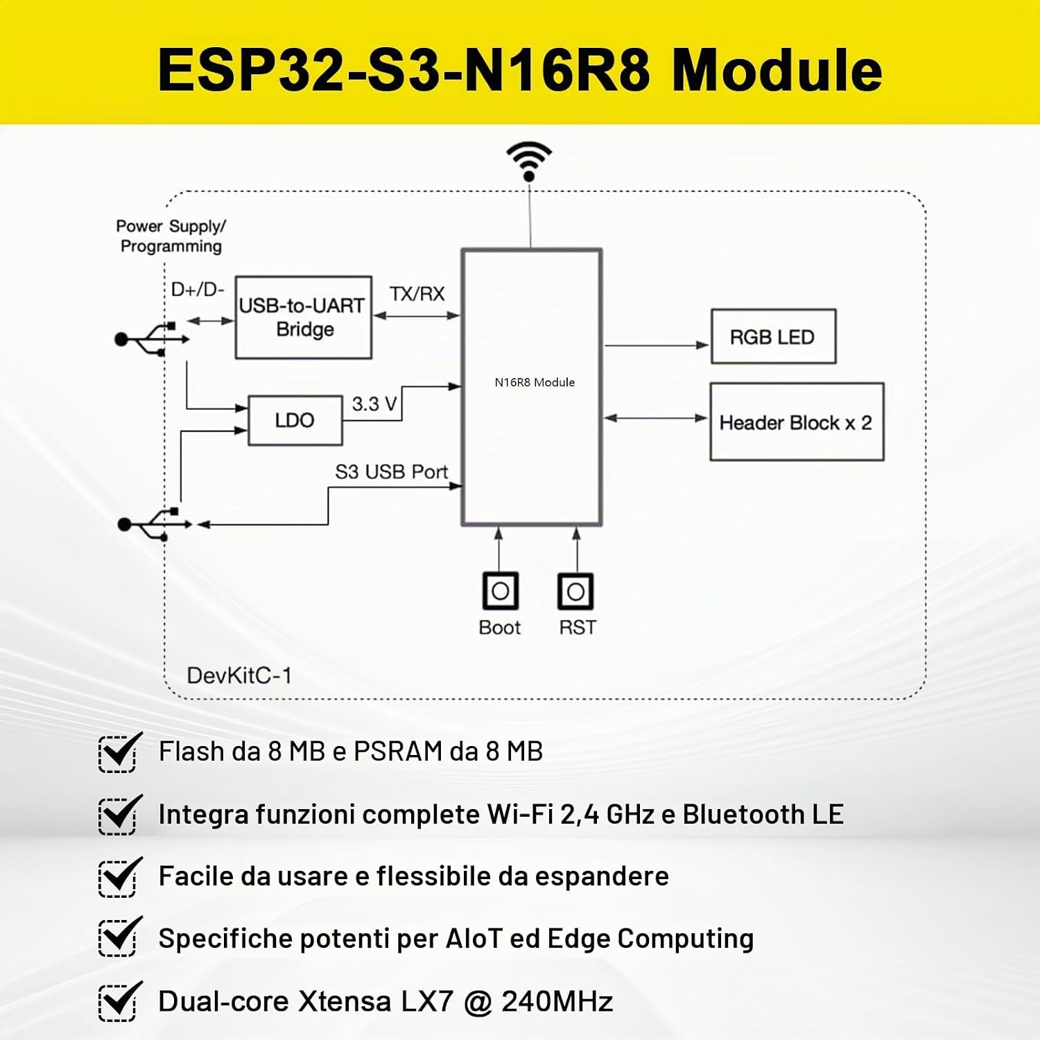
This block diagram provides a functional overview of the ESP32-S3-DevKitC-1. It shows how the N16R8 module interacts with other components like the USB-to-UART bridge for programming, the LDO for voltage regulation (3.3V), the RGB LED, and the header blocks for external connections. It also indicates the Boot and RST buttons for controlling the module's state. The diagram highlights key features such as 16MB Flash, 8MB PSRAM, integrated Wi-Fi and Bluetooth LE, and dual-core Xtensa LX7 @ 240MHz.
3. Specifications
| Model Name | ESP32-S3-DevKitC-1 |
| Chip Core | ESP32-S3 SoC, dual-core Xtensa LX7 at 240 MHz |
| Flash Memory | 16 MB |
| PSRAM | 8 MB |
| Wireless Connectivity | Wi-Fi: IEEE 802.11 b/g/n, 2.4 GHz, 20/40 MHz bandwidth (up to 150 Mbps) Bluetooth: Bluetooth 5 (LE), Bluetooth Mesh, PHY 125 Kbps/500 Kbps/1 Mbps/2 Mbps |
| AI Acceleration | Vector instructions, supports ESP-DSP and ESP-NN libraries |
| Security Features | AES-XTS flash encryption, RSA secure boot, HMAC, digital signature, hardware RNG |
| GPIO Pins | 45 programmable GPIOs |
| Digital Interfaces | 4 × SPI, 3 × UART, 2 × I²C, 2 × I²S, 1 × RMT, 1 × LCD interface, 1 × DVP camera interface |
| Analog Interfaces | 2 × 12-bit SAR ADC (up to 20 channels), 1 × temperature sensor, 14 × capacitive touch GPIOs |
| Other Interfaces | USB OTG, USB Serial/JTAG, MCPWM, SDIO host (2 slots), CAN (ISO11898-1), LED PWM (8 channels) |
| Timers | 4 × 54-bit general timers, 3 × watchdog timers, 1 × 52-bit system timer |
| Power Management | 5 power modes, ULP-RISC-V coprocessor for ultra-low power applications |
| USB Interface | Dual USB Type-C (supports UART and USB download modes) |
| Operating Voltage | 3.3 V (board powered via 5 V USB input) |
| Operating Temperature | -40 °C to +85 °C |
| Development Support | Arduino IDE, ESP-IDF framework |
| Compatible Devices | Arduino |
| Total USB Ports | 2 |
3.1 Dimensions

This image presents the physical dimensions of the RUIZHI ESP32-S3-N16R8 development board. It specifies the board's length as 57mm (2.24 inches), width as 28mm (1.10 inches), and height as 12mm (0.47 inches), along with pin spacing details. These measurements are crucial for integration into custom enclosures or projects.
4. Setup
4.1 Powering the Board
- Connect the board to a 5V USB power source using one of the two USB Type-C ports. The board operates at 3.3V internally.
- Ensure the power source can provide sufficient current for the board and any connected peripherals.
4.2 Connecting to a Computer
- Use a USB Type-C cable to connect the board to your computer. The board features dual Type-C ports; one typically functions as USB-to-Serial/JTAG for programming and debugging, and the other for USB OTG.
- Install the necessary USB drivers if your operating system does not automatically recognize the device.
4.3 Development Environment Setup
- Arduino IDE: Download and install the Arduino IDE. Add the ESP32 board support package through the Boards Manager. Select the appropriate ESP32-S3 board model.
- ESP-IDF: For advanced development, install the Espressif IoT Development Framework (ESP-IDF) by following the official Espressif documentation. This provides a robust environment for C/C++ development.
- Refer to the official documentation for ESP32-S3 for detailed instructions on setting up your preferred development environment.
5. Operating Instructions
5.1 Programming the Board
- Once your development environment is set up, write or load your code (sketch in Arduino, project in ESP-IDF).
- Connect the board to your computer via USB Type-C.
- Select the correct serial port for your board in the IDE.
- Upload the code to the board. The board may automatically enter bootloader mode, or you might need to press the BOOT button while pressing and releasing the RST button.
5.2 Using GPIOs and Peripherals
- The ESP32-S3-DevKitC-1-N16R8 offers 45 programmable GPIOs. Refer to the pinout diagram in Section 2.2 for pin assignments and capabilities.
- Utilize the various digital and analog interfaces (SPI, I²C, UART, ADC, PWM, etc.) to connect sensors, actuators, displays, and other modules.
- For wireless communication, use the integrated 2.4 GHz Wi-Fi and Bluetooth 5 (LE) capabilities to connect to networks or other Bluetooth devices.
5.3 AI and DSP Applications
- Leverage the ESP32-S3's vector instructions and support for ESP-DSP and ESP-NN libraries for AI and Digital Signal Processing tasks.
- This enables applications such as voice recognition, image processing, and neural network inference directly on the edge device.
6. Maintenance
- Handling: Handle the development board with care to avoid physical damage. Avoid bending the board or applying excessive force to components.
- Static Electricity: Always take precautions against electrostatic discharge (ESD) when handling the board, as electronic components are sensitive to static.
- Cleaning: If necessary, clean the board gently with a soft, dry brush or compressed air to remove dust. Avoid using liquids or harsh chemicals.
- Storage: Store the board in a dry, cool environment within the specified operating temperature range of -40 °C to +85 °C. Keep it away from direct sunlight and moisture.
- Power Supply: Always use a stable 5V power supply. Incorrect voltage can damage the board.
7. Troubleshooting
- Board Not Powering On: Ensure the USB Type-C cable is securely connected and the power source is active. Check if the PWR LED illuminates. Try a different USB cable or port.
- Upload Errors:
- Verify that the correct board and serial port are selected in your IDE.
- Ensure necessary drivers are installed.
- Try manually putting the board into bootloader mode by holding the BOOT button, pressing and releasing RST, then releasing BOOT.
- Check for any syntax errors in your code.
- Wi-Fi/Bluetooth Connectivity Issues:
- Confirm that your code correctly initializes and configures the Wi-Fi or Bluetooth module.
- Check network credentials (SSID, password) for Wi-Fi.
- Ensure the antenna is properly connected if external.
- Peripheral Not Responding:
- Double-check wiring connections to the GPIO pins.
- Verify that the correct GPIOs are configured in your code for the specific interface (SPI, I²C, UART).
- Ensure the peripheral itself is powered correctly and functioning.
- Unexpected Behavior: If the board behaves erratically, try resetting it using the RST button. If issues persist, re-upload a known working example sketch to rule out software problems.
8. Applications
The RUIZHI ESP32-S3-DevKitC-1-N16R8 development board is highly versatile and suitable for a wide array of applications, particularly in the fields of IoT and AIoT. Its powerful processing capabilities, extensive connectivity options, and AI acceleration features make it an excellent choice for:
- Smart Home Automation
- Industrial IoT (IIoT) Solutions
- Wearable Devices
- Robotics and Automation
- Voice Recognition Systems
- Image Processing and Computer Vision
- Edge AI Applications
- Sensor Networks
- Educational Projects

This image showcases various potential applications for the ESP32-S3-N16R8 development board. It illustrates its use in smart home systems for controlling devices, voice recognition applications, integrating sensors with Edge AI for intelligent data processing, and industrial automation scenarios. These examples highlight the board's versatility for IoT and AIoT projects.
9. Warranty and Support
For specific warranty information, please refer to the product packaging or the retailer's terms of sale. For technical support, documentation, and community forums, please visit the official RUIZHI website or the Espressif Systems documentation for the ESP32-S3 series.