
1. Introduction
This manual provides essential information for the safe and effective operation, setup, and maintenance of your PUWU MIG-160PRO 160Amp Multiprocess Welder. This versatile machine supports Gas MIG, Flux Core Gasless MIG, Lift TIG, and MMA/Stick welding processes. Please read this manual thoroughly before use to ensure proper functionality and safety.

Image 1.1: The PUWU MIG-160PRO welder demonstrating its four primary welding capabilities: Flux MIG, Stick, MIG, and Lift TIG.
2. Safety Information
WARNING: Welding can be dangerous. Always follow safety precautions to prevent injury or death.
- Always wear appropriate personal protective equipment (PPE), including a welding helmet with proper shade, flame-resistant clothing, welding gloves, and safety shoes.
- Ensure adequate ventilation to avoid inhaling welding fumes.
- Protect bystanders from arc rays and hot metal.
- Disconnect power before performing any maintenance or changing accessories.
- Do not operate the welder in damp or wet conditions.
- Ensure the work area is free of flammable materials.
- This machine is equipped with over-current, over-load, over-heating, and voltage fluctuation protections. Do not bypass these safety features.
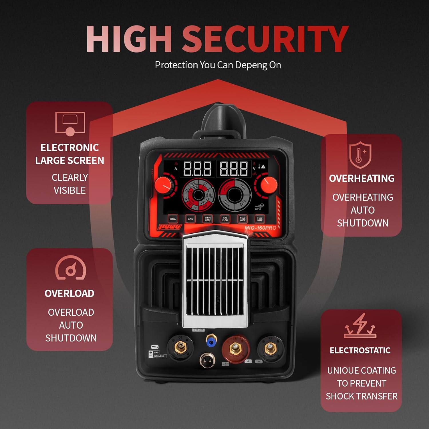
Image 2.1: Overview of the MIG-160PRO's integrated safety features, including electronic display, overheating protection, overload protection, and electrostatic shock prevention.
3. Package Contents
Verify that all items listed below are included in your package:
- PUWU MIG-160PRO Welder Unit
- 3 m Electrode Holder with red 10-25 connector
- 3 m Ground Clamp with black 10-25 connector
- One Wire-Feed Roller
- 2.2 m MB-11 MIG Torch (gas type)
- 2.5 m Black Double-Threaded Plastic Gas Hose
- U.S. Power Cord with Conversion Cable
- PUWU Instruction Manual
Note: Lift TIG torch is not included and must be purchased separately if required.
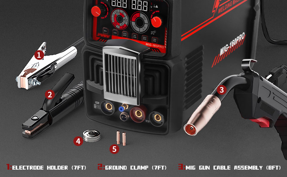
Image 3.1: The standard accessory package for the MIG-160PRO welder.
4. Product Overview
4.1 Control Panel and Features
The MIG-160PRO features an advanced LED digital display and intuitive controls for easy operation. The main control panel allows selection of welding mode, wire diameter, gas flow, and adjustment of current and voltage.

Image 4.1: Detailed view of the control panel, indicating the function of each knob and button.
- Left Knob/Button: Controls the welding current.
- Right Knob: Controls the welding voltage.
- Wire Diameter Selector (DIA.): Selects the appropriate wire diameter (.030"/.035"/.040").
- Gas Button (GAS): Activates or deactivates gas flow for MIG welding.
- Steps Mode (2T/4T/Automatic/Non-automatic): Selects trigger mode for MIG torch.
- Gas Flow (GAS FLOW): Adjusts gas flow rate.
- Weld Mode (WELD MODE): Selects between Gas MIG, Flux Core, Lift TIG, and Stick welding.
- Feed Wire (FEED WIRE): Manually feeds welding wire.
4.2 Portability and Design
Weighing approximately 15.3 lb (6.95 kg) and measuring 16.7" x 7.3" x 13.4", this welder is designed for portability. Its compact size and sturdy handle allow for easy transport to various job sites.

Image 4.2: The compact dimensions and lightweight design of the MIG-160PRO, emphasizing its portability.
5. Setup
5.1 Power Connection
The MIG-160PRO operates on dual voltage (110V/220V). Connect the appropriate power cord to a suitable power outlet. A 40A–50A circuit breaker is recommended for stable welding performance.
5.2 Wire Installation (MIG/Flux Core)
- Open the wire feed compartment.
- Place the wire spool onto the spindle, ensuring it rotates freely.
- Thread the welding wire through the wire guide and into the drive roller mechanism.
- Close the drive roller tension arm and adjust tension as needed.
- Press the 'Feed Wire' button on the control panel to feed the wire through the MIG torch liner until it exits the contact tip.
Video 5.1: Demonstration of how to install the welding wire into the MIG-160PRO welder.
5.3 Gas Connection (Gas MIG)
For Gas MIG welding, connect the gas hose from your shielding gas cylinder (e.g., Argon/CO2 mix) to the gas inlet on the rear of the welder. Ensure all connections are secure and leak-free.
5.4 Electrode Holder and Ground Clamp Connection
Connect the electrode holder (for Stick welding) or the MIG torch (for MIG/Flux Core) to the positive (+) terminal and the ground clamp to the negative (-) terminal for most applications. For Flux Core welding, ensure the polarity is set correctly (often electrode holder to negative, ground clamp to positive, refer to wire manufacturer specifications).

Image 5.1: Exploded view of the MIG torch head components, including the nozzle, electrode, and torch head.
6. Operating Modes
The MIG-160PRO offers four welding modes:
6.1 Gas MIG Welding
Use for welding with shielding gas. Select 'Gas MIG' mode, set wire diameter, and adjust current/voltage. Ensure gas flow is active.
6.2 Flux Core Gasless MIG Welding
Use for welding without external shielding gas, utilizing flux-cored wire. Select 'Flux Core' mode, set wire diameter, and adjust current/voltage. Verify correct polarity for flux core wire.
6.3 Lift TIG Welding
For precise welding with a TIG torch (not included). Select 'Lift TIG' mode. The arc is initiated by touching the tungsten electrode to the workpiece and then lifting it slightly. Requires external shielding gas (Argon).
6.4 Stick (MMA) Welding
For welding with coated electrodes. Select 'Stick' mode. Connect the electrode holder and ground clamp, then insert the appropriate electrode. Adjust current based on electrode type and size.
6.5 Synergic and Manual Control
The welder features synergic control, which automatically matches voltage and wire feeding speed to the selected wire diameter, simplifying setup for beginners. Experienced welders can switch to manual mode for precise customization of parameters.

Image 6.1: Examples of materials that can be welded with the MIG-160PRO, including cast iron, stainless steel, carbon steel, square pipe, and sheet metal.
7. Welding Parameters
Refer to the following tables for recommended welding parameters. These are general guidelines; actual settings may vary based on material thickness, joint type, and operator skill.

Image 7.1: Detailed welding parameter chart for MIG, ARC, and Lift TIG functions across 110V and 220V inputs.
| Parameter | MIG Function | ARC Function | Lift TIG Function | |||
|---|---|---|---|---|---|---|
| 110VAC | 220VAC | 110VAC | 220VAC | 110VAC | 220VAC | |
| Power Supply Voltage (V) | 29.4 | 19 | 32.5 | 22.5 | 23.9 | 16.2 |
| Rated Input Power (KW) | 4.1 | 5.5 | 4.6 | 6.3 | 3.4 | 4.4 |
| Rated Input Current (A) | 38 | 25 | 42 | 29 | 31 | 21 |
| Duty Cycle (40°C 10MIN) | 20% | |||||
| No-Load Voltage (V) | 60V | |||||
| Welding Current Range (A) | 40-120 | 40-160 | 20-120 | 20-160 | 20-120 | 20-160 |
| Welding Voltage Range (V) | 16-20 | 16-22 | 20.8-24.8 | 20.8-26.4 | 10.4-14.8 | 10.8-16 |
| Welding Wire Size Range | 0.8-0.9mm | 2.5-3.2mm | 1.0-2.0mm | |||
| Maximum Wire Feed Speed | 2-13 m/min | |||||
| Operating Temp | -20°C to +45°C | |||||
8. Maintenance
Regular maintenance ensures the longevity and optimal performance of your welder.
- Cleaning: Periodically clean the internal components with compressed air to remove dust and debris. Ensure the power is disconnected before cleaning.
- Cable Inspection: Regularly inspect all cables (power, electrode, ground, MIG torch) for cuts, fraying, or damage. Replace damaged cables immediately.
- MIG Torch Maintenance: Clean the nozzle, contact tip, and diffuser regularly. Replace worn contact tips and liners as needed to ensure smooth wire feeding.
- Ground Clamp: Ensure the ground clamp makes good electrical contact with the workpiece. Clean any rust or paint from the contact area.
- Storage: Store the welder in a clean, dry environment when not in use.
9. Troubleshooting
This section addresses common issues you might encounter. For problems not listed here, contact customer support.
| Problem | Possible Cause | Solution |
|---|---|---|
| Welder does not power on | No power from outlet; Power cord damaged; Internal fuse blown | Check power outlet and circuit breaker; Inspect power cord; Contact service center. |
| No arc/Poor arc stability | Improper ground connection; Incorrect welding parameters; Contaminated workpiece; Worn contact tip/electrode | Ensure good ground contact; Adjust current/voltage; Clean workpiece; Replace contact tip/electrode. |
| Wire feeding issues (MIG/Flux Core) | Incorrect drive roller tension; Kinked liner; Wrong size contact tip; Spool tangled | Adjust drive roller tension; Inspect and straighten liner; Use correct contact tip; Untangle wire spool. |
| Overheating protection activated | Exceeded duty cycle; Insufficient ventilation | Allow welder to cool down; Ensure clear airflow around the machine. |
10. Specifications
- Model: MIG-160PRO
- Input Voltage: 110V/220V Dual Voltage
- Welding Processes: Gas MIG, Flux Core Gasless MIG, Lift TIG, MMA/Stick
- Item Weight: Approximately 15.3 lb (6.95 kg)
- Product Dimensions: 16.7 x 7.3 x 13.4 inches
- Material: Metal, Plastic
- Cooling Mode: Fan Cooling
- Insulation Grade: F
- Protection Class: IP21S
11. Warranty and Support
For warranty information, please refer to the documentation provided at the time of purchase or contact your retailer. If you require technical assistance, troubleshooting, or have questions regarding your PUWU MIG-160PRO welder, please contact PUWU customer support through the official website or your purchase platform.