
1. Introduction
Thank you for choosing the LIGHTEU GLEDOPTO GL-DM-001W WiFi 5-Channel LED Dimmer Module. This module is designed for controlling various LED strips, including RGB, RGBW, and CCT types, leveraging the popular WLED platform and ESP32 technology. It offers flexible lighting solutions for smart home environments. This manual provides essential information for safe installation, configuration, and operation of your device.
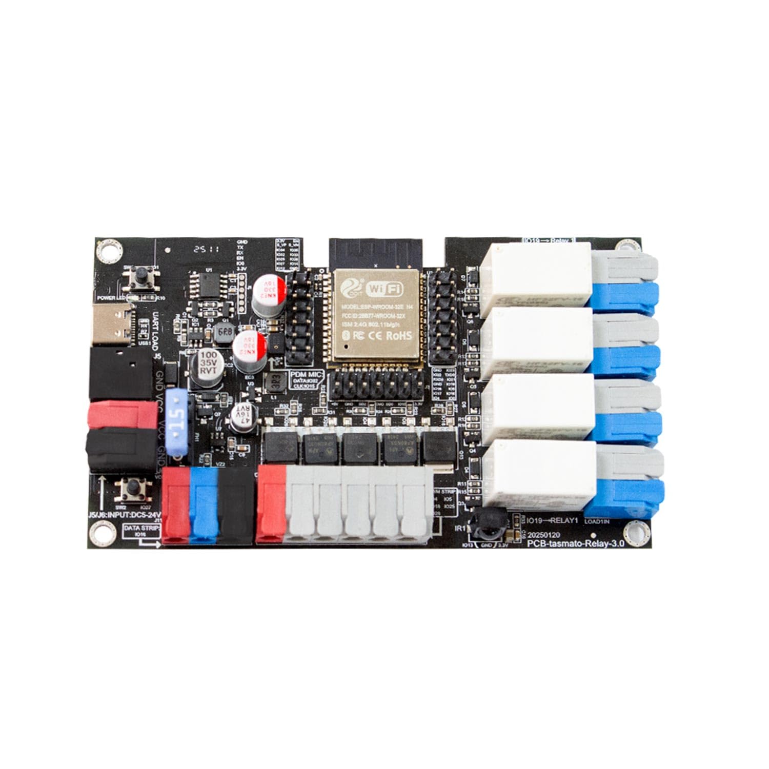
Figure 1: LIGHTEU GLEDOPTO GL-DM-001W Module Overview
2. Product Features
The GL-DM-001W module offers a range of features for advanced LED control:
- WiFi LED Dimmer Module: Controls RGB, RGBW, and CCT LED strips via the WLED platform.
- ESP32 Compatibility: Compatible with GLEDOPTO WLED controllers and all ESP32-based systems, supporting smart home integration.
- 5 Independent PWM Channels: Allows flexible configuration for RGB, RGBW, or RGB+CCT lighting solutions.
- Stable Performance: Operates with a DC 12-24V input voltage and up to 15A total current, suitable for powerful LED installations.
- Easy Configuration: Setup via WLED-AP hotspot, application, or web browser; no additional gateway or hub required.
- Equipped with Infrared Receiver: For remote control capabilities.
- Built-in Microphone: For audio-reactive lighting effects.
- Supports Digital LED Strips: Versatile compatibility.
- 4-Channel Relay Switch: For additional control options.
- 10A Fuse: Provides protection for the circuit.
- Type-C Port: For power or data.
- DIY GPIO Interface: For custom extensions and integrations.

Figure 2: Key Advantages of the GL-DM-001W Module
3. Technical Specifications
| Feature | Specification |
|---|---|
| Model Number | GL-DM-001W |
| Input Voltage | DC 12-24 V |
| Total Current Output | Up to 15 A |
| Number of PWM Channels | 5 |
| Connectivity Protocol | WiFi (ESP32) |
| Control Method | Application, Web Browser, Remote Control (via IR receiver) |
| Compatible Devices | RGB, RGBW, CCT LED Strips, WLED, Smart Home Systems |
| Dimensions (L x W x H) | 11 x 5 x 2 cm (107mm x 61mm x 20mm) |
| Weight | 77g (Net), 88.2g (Gross) |
| Material | Acrylonitrile Butadiene Styrene (ABS), Aluminum |
| IP Rating | IP20 |
| Operating Mode | ON-OFF |
| Current Rating | 10 A |

Figure 3: Module Dimensions (107mm x 61mm x 20mm)
4. Setup and Installation
Follow these steps to correctly install and connect your GL-DM-001W module.
4.1. Power Supply Connection
Connect your DC 12-24V power supply to the designated input terminals on the module. Ensure correct polarity (positive to +V, negative to GND). The module supports an input current of up to 10A Max.
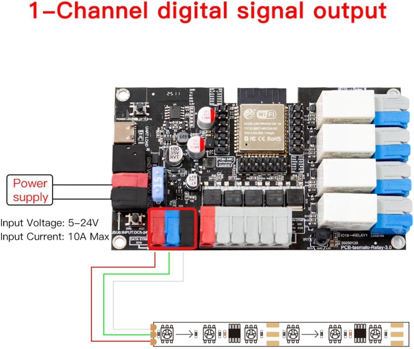
Figure 4: Power Supply and 1-Channel Digital Signal Output Connection
4.2. 5-Channel PWM Output Connection
For RGB, RGBW, or CCT LED strips, connect the respective channels (R, G, B, W, CCT) to the 5-channel PWM output terminals. Ensure that the common anode or common cathode of your LED strip matches the module's configuration.

Figure 5: 5-Channel PWM Output Connection to LED Strip
4.3. 1-Channel Digital Signal Output Connection
If using digital LED strips (e.g., WS2811, WS2812, SK6812), connect the data line to the designated 1-channel digital signal output terminal. Refer to Figure 4 for the connection point.
4.4. 4-Channel Relay Switch Connection
The module includes a 4-channel relay switch. Connect your loads to these relays as needed. An independent Type-C interface is available for power supply to the relay switch if required. Input voltage for the relay is 5V, with a minimum input current of 1A.

Figure 6: 4-Channel Relay Switch Connections and WLED Configuration
4.5. Additional GPIO Ports
The module provides additional GPIO ports for advanced users and custom integrations. These ports allow for extended functionality and connectivity with other components.

Figure 7: Additional GPIO Ports Layout
4.6. Pin Header
The module features a 2.54mm pitch pin header for various connections. Dupont wires (not included) can be used for these connections.

Figure 8: Pin Header and Included Accessories
5. Operating Instructions
The GL-DM-001W module is primarily controlled via the WLED platform, accessible through a web browser or dedicated application.
5.1. WLED Configuration
Upon initial power-up, the module will create a WLED-AP hotspot. Connect to this hotspot using a Wi-Fi enabled device (smartphone, computer) and navigate to the WLED configuration page in your web browser. Here you can set up your Wi-Fi network, LED preferences, and other settings. The WLED application provides a user-friendly interface for controlling colors, effects, and segments.

Figure 9: WLED Application Configuration Flow
5.2. Microphone Configuration
The built-in microphone allows for audio-reactive lighting effects. Within the WLED application or web interface, navigate to the 'Sound Settings' or 'Audio Reactive' section to configure microphone sensitivity, gain, and other audio-related parameters. This enables your LED strips to respond dynamically to sound.
5.3. Relay Function Configuration
To utilize the 4-channel relay switch, configure its functions within the WLED interface. You can assign specific GPIO pins to control the relays. When using the relay function, it may be necessary to enable the 'relay reverse function' in WLED settings to ensure correct operation (refer to Figure 6, point 2).
6. Maintenance
The GL-DM-001W module requires minimal maintenance. Keep the device clean and free from dust. Use a dry, soft cloth for cleaning. Avoid exposing the module to moisture, extreme temperatures, or corrosive substances. Ensure proper ventilation to prevent overheating, especially during prolonged operation at high loads.
7. Troubleshooting
If you encounter issues with your GL-DM-001W module, consider the following:
- No Power: Verify that the power supply is correctly connected and providing the specified DC 12-24V. Check the fuse for continuity.
- No Wi-Fi Connection: Ensure the module is within range of your Wi-Fi router. If setting up for the first time, connect to the WLED-AP hotspot. If already configured, check your router settings and ensure the module's Wi-Fi credentials are correct.
- LEDs Not Responding: Check all wiring connections to the LED strips for correct polarity and secure contact. Verify that the LED type is correctly configured in WLED.
- Incorrect Colors/Effects: Review your WLED settings for LED preferences, color order, and effect selections.
- Relay Not Activating: Ensure the relay is correctly wired and powered. Check WLED settings for relay GPIO assignments and consider enabling the 'relay reverse function' if needed.
- Module Overheating: Ensure adequate ventilation around the module. Reduce the load if operating at maximum capacity for extended periods.
8. Safety Information
Please observe the following safety precautions:
- Electrical Safety: Always disconnect power before making any connections or performing maintenance. Improper wiring can cause damage to the device or pose an electrical hazard.
- Voltage Compatibility: Use only power supplies within the specified DC 12-24V range. Exceeding this voltage will damage the module.
- Indoor Use Only: This device is rated IP20 and is intended for indoor use in dry environments. Do not expose to water or high humidity.
- Professional Installation: If you are unsure about electrical wiring, consult a qualified electrician.
- Avoid Short Circuits: Ensure all connections are secure and there are no exposed wires that could cause a short circuit.
- Children and Pets: Keep the device out of reach of children and pets.
9. Warranty and Support
For warranty information and technical support, please refer to the documentation provided with your purchase or contact LIGHTEU customer service. Keep your proof of purchase for warranty claims.