
1. Introduction
This manual provides essential information for the safe and efficient operation, maintenance, and troubleshooting of your MechMaxx VM32L Industrial Benchtop Mill Drill Machine. Please read this manual thoroughly before operating the machine to ensure proper usage and to prevent injury or damage.
The MechMaxx VM32L is a versatile industrial benchtop mill drill machine designed for precision drilling, milling, and tapping operations in various metalworking applications. It features a powerful brushless motor, variable speed control, and an R8 spindle for broad tool compatibility.
2. Safety Instructions
WARNING: Failure to follow these safety instructions may result in serious injury or death.
- Always wear appropriate personal protective equipment (PPE), including safety glasses, hearing protection, and sturdy footwear.
- Ensure the machine is properly grounded and connected to a 110V power supply.
- Keep the work area clean and well-lit. Cluttered areas invite accidents.
- Do not operate the machine under the influence of drugs, alcohol, or medication.
- Securely clamp all workpieces before beginning any operation.
- Never leave the machine unattended while it is running.
- Disconnect power before performing any adjustments, maintenance, or when changing tools.
- Keep hands and clothing clear of moving parts.
- Refer to local safety regulations and guidelines for additional requirements.
3. Machine Components
Familiarize yourself with the main components of the MechMaxx VM32L mill drill machine.
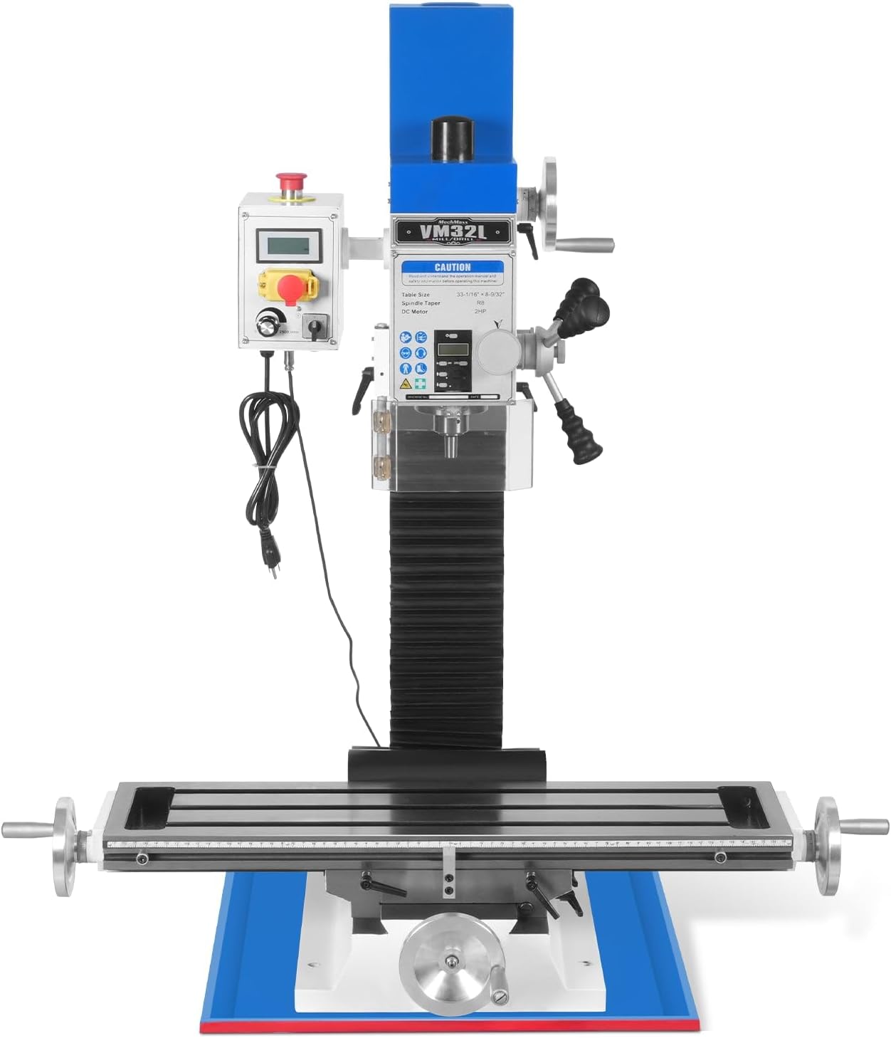
The machine features a robust construction with a square column and dovetail slide for stability and precision. Key components include:
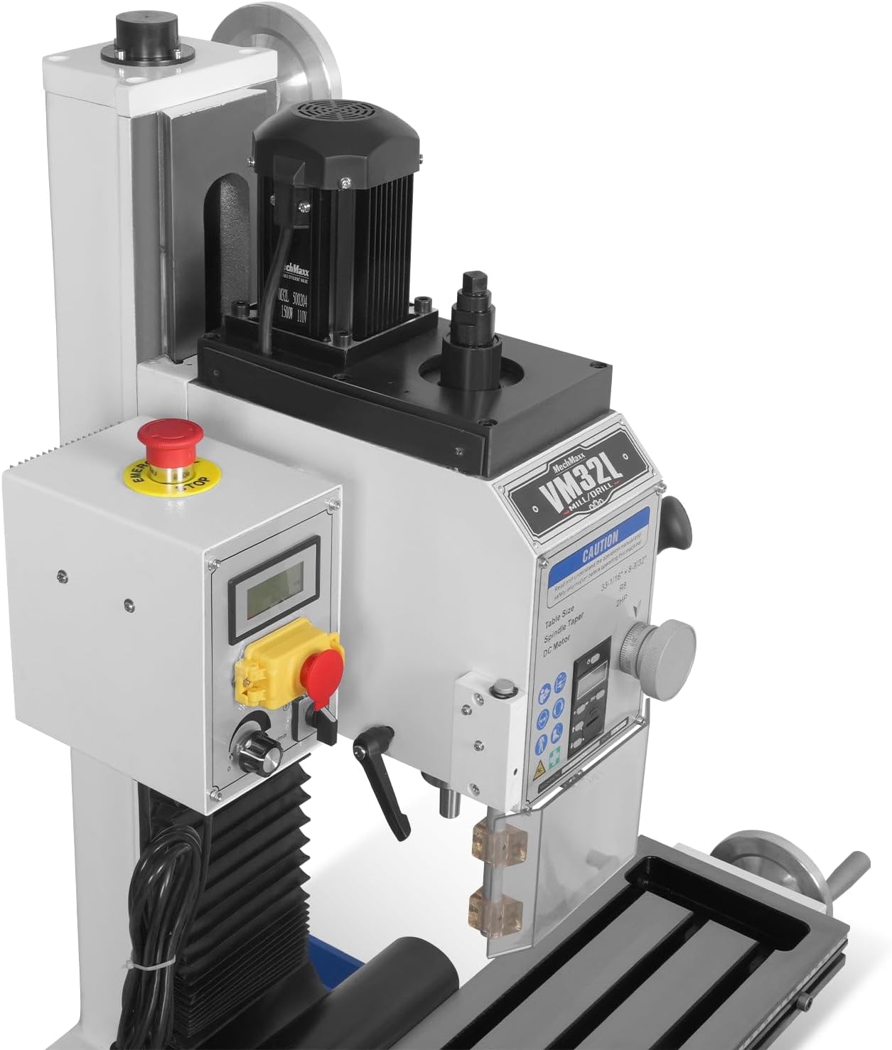
- Head Assembly: Contains the motor, spindle, and speed controls. It can tilt ±60° for angled operations.
- Control Panel: Houses the power switch, emergency stop button, variable speed dial, and digital readout (DRO) for spindle speed.
- Spindle: R8 taper for wide tool compatibility.
- Work Table: A 7-1/4" x 33" (180 x 700mm) table with T-slots for clamping workpieces.
- Handwheels: For precise control of X, Y, and Z axis movement.
- Brushless Motor: 2 HP motor providing smooth and quiet operation.

4. Setup and Installation
4.1 Unpacking and Inspection
- Carefully remove the machine from its packaging.
- Inspect all components for any shipping damage. Report any damage to the carrier immediately.
- Verify that all included components are present as per the packing list.
4.2 Placement
- Place the mill drill machine on a sturdy, level workbench capable of supporting its weight (approximately 528 pounds).
- Ensure adequate clearance around the machine for safe operation and maintenance.
- The machine should be located in a dry, well-ventilated area, away from flammable materials.
4.3 Electrical Connection
- Connect the machine to a dedicated 110V, 60Hz, single-phase power outlet with appropriate circuit protection.
- Ensure the power cord is free from damage and properly routed to avoid tripping hazards.
4.4 Initial Lubrication
Before first use, apply a thin coat of machine oil to all unpainted metal surfaces, especially the dovetail ways and lead screws, to prevent corrosion and ensure smooth operation.

5. Operating Instructions
5.1 Basic Operation
- Power On: Turn the main power switch to the "ON" position. The digital readout (DRO) should illuminate.
- Tool Installation: Insert the desired R8 taper tool into the spindle. Ensure it is seated correctly and tightened securely.
- Workpiece Clamping: Securely clamp your workpiece to the work table using appropriate clamps or a vise.
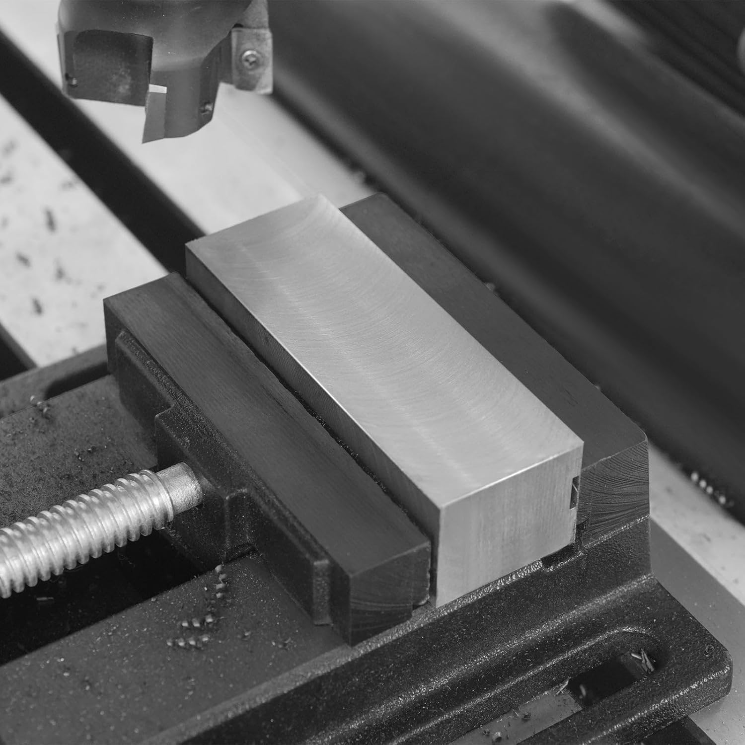
Figure 5.1: A workpiece securely clamped in a vise on the machine table. - Speed Adjustment: Use the variable speed dial on the control panel to set the appropriate spindle speed for your material and tool. The DRO provides real-time speed feedback.
- Axis Movement: Use the X, Y, and Z axis handwheels to position the workpiece relative to the tool. The 3-axis DRO system provides precise digital measurements.

Figure 5.2: X-axis and Y-axis travel dimensions for the work table. 
Figure 5.3: Handwheels provide fine control over axis movements. - Engage Spindle: Press the spindle start button. For hands-free spindle direction control, an optional foot pedal may be used.

Figure 5.4: Optional hands-free spindle direction control. - Perform Operation: Slowly feed the tool into the workpiece using the Z-axis handwheel or micro-feed mechanism. Monitor the clear spindle travel readout for depth control.

Figure 5.5: Spindle travel readout and micro-feed for precise depth control. - Emergency Stop: In case of an emergency, press the red emergency stop button on the control panel.
5.2 Drilling Operations
- Select the appropriate drill bit for the material and desired hole size.
- Set the spindle speed according to material recommendations.
- Use the adjustable depth stop for consistent hole depths.

Figure 5.6: The adjustable depth stop ensures repeatable drilling depths. - The machine is capable of drilling up to 1-1/4" (32mm).
5.3 Milling Operations
- Choose the correct end mill or face mill for the task.
- Adjust the spindle speed and feed rate for optimal material removal.
- The machine supports end milling up to 3/4" (20mm) and face milling up to 3" (76mm).
- Utilize the ±60° tilting head for angled cuts and complex milling.

6. Maintenance
WARNING: Always disconnect the machine from the power source before performing any maintenance.
6.1 Daily Maintenance
- Clean the work table and machine surfaces of chips and debris after each use.
- Wipe down exposed metal surfaces with a clean cloth and apply a light coat of oil to prevent rust.
6.2 Weekly Maintenance
- Inspect all moving parts, including lead screws and dovetail ways, for wear or damage.
- Lubricate the lead screws and dovetail ways with appropriate machine grease or oil.
- Check and tighten any loose fasteners.
6.3 Periodic Checks
- Inspect the electrical cord and connections for signs of wear or damage.
- Check the spindle for any excessive runout.
- Ensure the emergency stop button functions correctly.

7. Troubleshooting
This section outlines common issues and their potential solutions. If you encounter problems not listed here or if solutions do not resolve the issue, contact customer support.
| Problem | Possible Cause | Solution |
|---|---|---|
| Machine does not power on. | No power supply; Emergency stop engaged; Faulty switch. | Check power connection; Disengage emergency stop; Contact support. |
| Spindle does not rotate. | Motor overload; Incorrect speed setting; Loose wiring. | Reduce load; Adjust speed; Check connections (qualified personnel only). |
| Excessive vibration or noise. | Unbalanced tool; Loose workpiece; Worn bearings. | Balance tool; Secure workpiece; Contact support for bearing inspection. |
| Inaccurate cuts/drills. | Loose gibs; Worn lead screws; Improper tool setup. | Adjust gibs; Inspect lead screws; Verify tool installation and workpiece clamping. |
8. Specifications
| Feature | Detail |
|---|---|
| Brand | MechMaxx |
| Model Number | VM32L |
| Power Source | Corded Electric |
| Voltage | 110V |
| Motor | 2 HP Brushless DC Motor |
| Spindle Taper | R8 |
| Drilling Capacity | 1-1/4" (32mm) |
| End Milling Capacity | 3/4" (20mm) |
| Face Milling Capacity | 3" (76mm) |
| Head Tilt | ±60° |
| Work Table Size | 7-1/4" x 33" (180 x 700mm) |
| X-Axis Travel | 22-7/8" |
| Y-Axis Travel | 11-1/32" |
| Product Dimensions (L x W x H) | 28" x 47" x 45" |
| Item Weight | 528 pounds |
| Included Components | User Manual |
9. Warranty and Support
9.1 Warranty Information
For specific warranty details, please refer to the warranty card included with your product or contact MechMaxx customer service. Protection plans are available for purchase separately.
- 3-Year Protection Plan: Available for purchase.
- 4-Year Protection Plan: Available for purchase.
9.2 Customer Support
If you have questions, require technical assistance, or need to report an issue, please contact MechMaxx customer support. You can often find contact information on the manufacturer's website or through your purchase platform.
For more information, visit the official MechMaxx store: MechMaxx Store on Amazon.


