Introduction
The FNIRSI DS215H is a compact, portable 2-in-1 device integrating a dual-channel digital oscilloscope and a DDS signal generator. Designed for electronics enthusiasts, engineers, and students, it offers a 50 MHz bandwidth, 250 MS/s real-time sampling rate, and a 3.5-inch IPS color display. This manual provides detailed instructions for the safe and effective use of your DS215H device.
Please read this manual thoroughly before operating the device to ensure proper functionality and to prevent damage.
Safety Information
- Power Supply: Use only the specified Type-C (5V/1A) power supply for charging.
- Input Voltage: Do not exceed the maximum input voltage of ±400V (Peak) for the oscilloscope channels. Exceeding this limit can cause permanent damage to the device.
- Environment: Operate the device in a dry environment. Avoid exposure to moisture, dust, or extreme temperatures.
- Maintenance: Do not attempt to disassemble or modify the device. Refer all servicing to qualified personnel.
- Probes: Ensure oscilloscope probes are correctly connected and rated for the voltage being measured.
Product Overview
The FNIRSI DS215H features a user-friendly interface with a 3.5-inch IPS display, dual control knobs, and intuitive buttons for navigation and parameter adjustment. The device integrates both oscilloscope and signal generator functionalities into a single portable unit.

Image 1: The FNIRSI DS215H handheld oscilloscope and signal generator, shown with its included accessories such as oscilloscope probes, USB-C charging cable, and BNC-to-alligator clip cable.
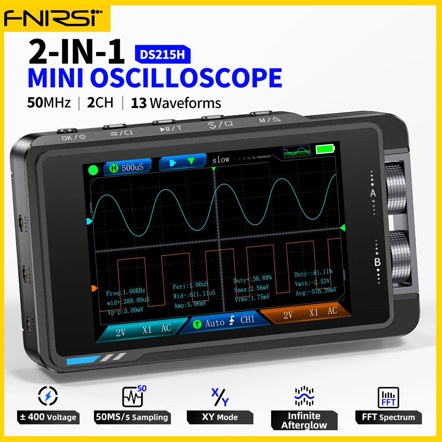
Image 2: The FNIRSI DS215H displaying a waveform, with text overlays highlighting its 50MHz bandwidth, 2 channels, and 13 waveform types for the signal generator.
Setup
- Unboxing: Carefully remove the DS215H and all accessories from the packaging. Inspect for any signs of damage.
- Charging: Connect the device to a 5V/1A Type-C power adapter using the provided USB cable. The battery indicator on the screen will show charging status. A full charge typically takes a few hours.
- Power On/Off: Press and hold the power button (usually labeled 'OK/⏻') for a few seconds to power on or power off the device.
- Language Settings: Upon first use or after a reset, you may need to select your preferred language. Navigate through the menu using the control knobs and buttons to find the language setting. Supported languages include Chinese, English, Russian, Japanese, Spanish, Portuguese, German, and Korean.
Operating Instructions
Oscilloscope Mode
- Connecting Probes: Connect the oscilloscope probes to the BNC input connectors (CH1, CH2) on the device. Ensure the probe's attenuation setting (e.g., 1X or 10X) matches the setting on the oscilloscope.
- Input Coupling: Select AC or DC coupling based on your measurement requirements. AC coupling blocks the DC component of the signal, while DC coupling shows the entire signal.
- Vertical Sensitivity (Volts/Div): Use the vertical control knob to adjust the vertical scale (10 mV/div – 10 V/div). This determines the voltage represented by each vertical division on the screen.
- Time Base (Time/Div): Use the horizontal control knob to adjust the time base (20 ns/div – 20 s/div). This determines the time represented by each horizontal division on the screen.
- Trigger Settings:
- Trigger Type: Select between Rising Edge or Falling Edge to trigger on the positive or negative slope of the signal.
- Trigger Level: Adjust the trigger level to stabilize the waveform. The trigger level range is 8 divisions.
- Trigger Modes: Choose from Auto (triggers automatically), Normal (triggers only when conditions are met), or Single (captures a single event).
- Display Modes: The DS215H supports Y-T (standard time-domain display), X-Y (for Lissajous figures), and Roll modes.
- Measurements: The device can automatically measure various parameters including Period, Frequency, Peak-to-Peak Voltage, Maximum Voltage, Minimum Voltage, Average Voltage, RMS Voltage, Amplitude, Duty Cycle, and Pulse Width.
- Waveform Storage and Export: The device supports storing captured waveforms internally and exporting them for further analysis. Refer to the on-screen menu for specific instructions on saving and exporting.

Image 3: The FNIRSI DS215H displaying two distinct waveforms simultaneously on its dual channels, illustrating its dual-channel capability.

Image 4: The FNIRSI DS215H displaying multiple waveforms, emphasizing its FPGA+MCU+ADC hardware architecture for high performance and support for various measurements and math functions.

Image 5: The FNIRSI DS215H showcasing its multiple interface display options, including standard oscilloscope view, DDS signal generator interface, XY mode, FFT spectrum analysis, and cursor measurement.
Signal Generator Mode
The DS215H includes a built-in DDS signal generator capable of producing various waveforms.
- Accessing Generator: Navigate to the signal generator function through the device's menu.
- Output Waveforms: Select from 13 available waveform types, such as Sine Wave, Square Wave, Sawtooth Wave, and Half Wave.
- Frequency Adjustment: Adjust the output frequency within the range of 0 – 50 kHz using the control knobs.
- Amplitude Adjustment: Set the output amplitude from 0.1 V – 3.0 V.
- Duty Cycle (Square Wave): For square waves, adjust the duty cycle from 0 – 100%.

Image 6: The FNIRSI DS215H displaying various signal waveforms generated by its DDS function, including Sine Wave, Square Wave, Sawtooth Wave, Half Wave, and Full Wave, with adjustable frequency and amplitude settings.
Maintenance
- Cleaning: Use a soft, dry cloth to clean the device. Do not use abrasive cleaners or solvents.
- Battery Care: To prolong battery life, avoid fully discharging the battery frequently. If storing the device for an extended period, charge it to approximately 50% and recharge every few months.
- Storage: Store the device in a cool, dry place away from direct sunlight and extreme temperatures.
- Firmware Updates: Check the manufacturer's official website periodically for any available firmware updates to ensure optimal performance and access to new features.
Troubleshooting
- Device Not Powering On: Ensure the battery is charged. Connect the device to a power source and try again. If the issue persists, contact support.
- No Waveform Displayed:
- Check probe connections and ensure they are securely attached to the input.
- Verify the probe attenuation setting matches the device setting.
- Adjust the vertical sensitivity (Volts/Div) and time base (Time/Div) to appropriate ranges for the expected signal.
- Check trigger settings; an incorrect trigger level or mode can prevent a stable display. Try 'Auto' trigger mode initially.
- Inaccurate Measurements:
- Ensure probes are properly calibrated (if applicable).
- Check for external interference or noise in the measurement environment.
- Signal Generator Output Issues: Verify the frequency, amplitude, and waveform type settings are correctly configured. Ensure the output is connected to the intended load.
Specifications
| Feature | Specification |
|---|---|
| Display | 3.5-inch IPS high-resolution color screen |
| Backlight | Adjustable brightness |
| Power Supply | Type-C (5V/1A) |
| Battery Capacity | 1500 mAh Lithium Polymer |
| Dimensions | ≈ 66 × 110 × 19.5 mm (4.33 x 2.6 x 0.77 inches) |
| Net Weight | ≈ 138 g (5.2 ounces) |
| Languages Supported | Chinese, English, Russian, Japanese, Spanish, Portuguese, German, Korean |
| Feature | Specification |
|---|---|
| Channels | Dual-channel |
| Bandwidth | 50 MHz |
| Real-Time Sampling Rate | 250 MSa/s |
| Memory Depth | 14 Mpts |
| Time Base Range | 20 ns/div – 20 s/div |
| Vertical Sensitivity | 10 mV/div – 10 V/div |
| Display Modes | Y-T, X-Y, Roll |
| Vertical Resolution | 8-bit |
| Impedance | 1 MΩ |
| Measurements | Period, Frequency, Peak-to-Peak Voltage, Maximum, Minimum, Average, RMS, Amplitude, Duty Cycle, Pulse Width |
| Probe Attenuation Coefficient | 1X / 10X |
| Input Coupling | AC / DC |
| Trigger Types | Rising Edge / Falling Edge |
| Maximum Input Voltage (Peak) | ±400 V |
| Trigger Level Range | 8 divisions |
| Trigger Modes | Auto / Normal / Single |
| Feature | Specification |
|---|---|
| Output Waveforms | Multiple waveform types supported (13 types) |
| Frequency Range | 0 – 50 kHz |
| Square Wave Duty Cycle | 0 – 100% |
| Amplitude Range | 0.1 V – 3.0 V |
Warranty Information
FNIRSI products are typically covered by a limited warranty against defects in materials and workmanship. The specific terms and duration of the warranty may vary by region and retailer. Please retain your proof of purchase for warranty claims. For detailed warranty information, refer to the warranty card included with your product or visit the official FNIRSI website.
Support
For technical assistance, troubleshooting, or product inquiries, please contact FNIRSI customer support. Support contact information can usually be found on the official FNIRSI website or on the product packaging. When contacting support, please have your product model (DS215H) and purchase details ready.


