
1. Introduction
This manual provides essential information for the safe and efficient installation, operation, and maintenance of the Delta VFD015EL21A VFD-EL Variable Frequency Drive. Please read this manual thoroughly before attempting to install or operate the unit. Retain this manual for future reference.
2. Safety Information
WARNING: Improper installation or operation may result in serious injury or death, and damage to equipment. Always observe the following safety precautions:
- Ensure power is disconnected before installation, wiring, or maintenance.
- Only qualified personnel should perform installation and wiring.
- Properly ground the VFD and motor to prevent electrical shock.
- Do not touch internal components or circuit boards when power is applied.
- Verify correct voltage and current ratings before connecting power.
- Protect the unit from moisture, dust, and corrosive gases.
3. Product Overview
The Delta VFD015EL21A is a 2HP (1500W) Variable Frequency Drive designed for precise motor control. It operates on a 230V AC power supply and delivers up to 7.5A output current. This compact unit supports both chassis and DIN rail mounting, and includes an RS-485 interface for communication with automation systems.
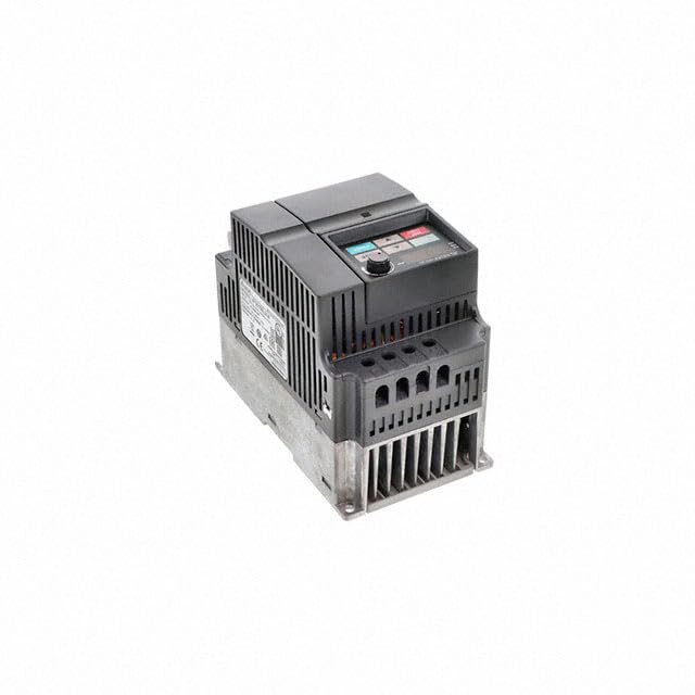
Figure 3.1: Front view of the Delta VFD015EL21A VFD-EL Variable Frequency Drive, showing the LED display and control buttons.
4. Setup
4.1 Unpacking and Inspection
Upon receiving the VFD, carefully unpack it and inspect for any signs of damage during transit. Verify that all components are present according to the packing list. If any damage or missing parts are found, contact your supplier immediately.
4.2 Mounting
The VFD015EL21A offers flexible mounting options:
- DIN Rail Mounting: Attach the VFD directly to a standard 35mm DIN rail. Ensure it clicks securely into place.
- Chassis Mounting: Use screws to secure the VFD to a panel or enclosure. Ensure adequate ventilation space around the unit (minimum 50mm clearance above and below, 10mm on sides).
Mount the VFD vertically to optimize heat dissipation. Avoid mounting in direct sunlight or near heat sources.
4.3 Wiring
All wiring must be performed by a qualified electrician. Ensure power is disconnected before wiring.
- Power Input (L1, L2): Connect the 230V AC single-phase power supply to the L1 and L2 terminals. Use appropriate wire gauges as specified in the technical documentation.
- Motor Output (U, V, W): Connect the three-phase motor leads to the U, V, and W terminals. Ensure correct phase sequence for desired motor rotation.
- Grounding (PE): Connect the protective earth (ground) terminal of the VFD to a reliable earth ground. This is critical for safety.
- Control Terminals: Connect external control signals (e.g., start/stop, speed reference, fault reset) to the designated digital and analog input terminals. Relay outputs can be used for status indication. Refer to the detailed wiring diagram in the full product manual for specific terminal assignments.
- RS-485 Communication (A+, B-): For remote monitoring and control, connect the RS-485 communication lines to the A+ and B- terminals. Ensure proper termination resistors are used if required by the network configuration.
Note: A detailed wiring diagram is typically provided in the comprehensive product manual. Always refer to it for precise terminal connections and wire specifications.
5. Operating Instructions
5.1 Control Panel Overview
The VFD features an LED display and several buttons for local operation and parameter setting. The LED display shows operational status, frequency, current, and error codes. Buttons typically include RUN, STOP, PROGRAM, ENTER, UP, and DOWN.
5.2 Basic Operation
- Starting the Motor: Press the RUN button. The motor will accelerate to the set frequency.
- Stopping the Motor: Press the STOP button. The motor will decelerate and stop.
- Adjusting Speed: Use the UP and DOWN buttons to adjust the output frequency (motor speed) when in local control mode.
5.3 Parameter Settings
To access and modify VFD parameters:
- Press the PROGRAM button to enter parameter mode.
- Use the UP and DOWN buttons to navigate through parameter groups and individual parameters.
- Press ENTER to select a parameter and view its current value.
- Use UP and DOWN to change the value.
- Press ENTER again to save the new value.
- Press PROGRAM to exit parameter mode.
Refer to the VFD-EL Series User Manual for a complete list of parameters and their functions.
6. Maintenance
Regular maintenance ensures optimal performance and extends the lifespan of the VFD.
6.1 Routine Inspection
- Periodically check all wiring connections for tightness and signs of corrosion.
- Inspect the VFD for any unusual noises, vibrations, or odors.
- Monitor the operating temperature of the VFD and ensure proper ventilation.
6.2 Cleaning
With power disconnected, use compressed air to remove dust and debris from the VFD's heatsink and ventilation openings. Do not use liquid cleaners directly on the unit.
6.3 Environmental Considerations
Ensure the operating environment remains within the specified temperature range of -10°C to 50°C (14°F to 122°F) and appropriate humidity levels to prevent condensation.
7. Troubleshooting
This section provides guidance for common issues. For complex problems or error codes not listed, consult the comprehensive VFD-EL Series User Manual or contact technical support.
| Problem | Possible Cause | Solution |
|---|---|---|
| VFD does not power on | No input power; Blown fuse; Incorrect wiring | Check power supply; Replace fuse; Verify wiring connections |
| Motor does not run | Stop command active; Incorrect motor wiring; Parameter settings | Check control signals; Verify motor connections (U,V,W); Review run parameters |
| Motor runs at incorrect speed | Incorrect frequency reference; Parameter settings | Check speed reference input; Adjust frequency parameters (e.g., max frequency, acceleration/deceleration times) |
| VFD displays an error code | Overcurrent, Overvoltage, Overheat, etc. | Note the error code and consult the VFD-EL Series User Manual for specific troubleshooting steps. Address the underlying cause (e.g., motor overload, power supply issues). |
8. Specifications
| Specification | Value |
|---|---|
| Model Name | VFD015EL21A |
| Brand | Delta Electronics |
| Power Output | 2HP / 1500W |
| Output Current | 7.5A |
| Input Voltage | 230V AC |
| Power Source | AC Power |
| Inverter Capacity | 2000 VA |
| Electrical Output Waveform | Modified Sine Wave |
| Display Type | LED Display |
| Connectivity | RS-485 Interface |
| Mounting Options | Chassis Mount, DIN Rail Mount |
| Operating Temperature | -10°C to 50°C (14°F to 122°F) |
| Product Dimensions (L x W x H) | 8" x 4.5" x 12" |
| Item Weight | 6 Pounds |
| Manufacturer | Delta Electronics/Industrial Automation |
9. Warranty and Support
9.1 Warranty Information
No specific warranty description is provided with this product. For detailed warranty terms and conditions, please contact Delta Electronics directly or refer to the official product documentation provided at the time of purchase.
9.2 Technical Support
For technical assistance, troubleshooting beyond this manual, or inquiries regarding product functionality, please contact Delta Electronics customer support or visit their official website for resources and contact information.


