
1. Introduction
This manual provides detailed instructions for the installation, operation, and maintenance of the GRYVOZE 1/2 inch NPT Digital Gear Flow Meter, Model A3200. This device is designed for accurate measurement of low-flow, high-viscosity liquids in various industrial, automotive, and agricultural applications. Please read this manual thoroughly before use to ensure proper function and safety.
2. Safety Information
- Ensure the flow meter is installed by qualified personnel in accordance with local codes and regulations.
- Verify compatibility of the meter's materials with the liquid being measured to prevent corrosion or damage.
- Do not exceed the maximum pressure rating of 435 psi.
- Operate within the specified temperature range of -22 °F to 158 °F (-30 °C to 70 °C).
- Always depressurize the system before attempting installation, maintenance, or battery replacement.
- Protect the display from direct impact to prevent damage.
3. Product Overview
3.1 Key Features
- Multi-Mode Display: Supports Shift Cumulative Flow, Total Cumulative Flow, and Instantaneous Flow readings.
- High Accuracy: Provides ±0.5% measuring accuracy for stable and precise readings.
- Wide Application: Suitable for motor oil, lubricants, transmission fluid, antifreeze, and other high-viscosity or low-flow liquids.
- Anti-Electromagnetic Interference: Operates stably near motors, welders, or high-frequency power sources.
- Energy-Saving Design: Automatic power-off after 1 minute of inactivity, with data retention and bidirectional flow measurement support.
- Durable Construction: One-piece die-cast aluminum alloy body with IP68 waterproof rating.
3.2 Components
The GRYVOZE Digital Gear Flow Meter consists of an integrated die-cast aluminum alloy body, high-precision measuring gears, and a rotatable LCD screen for clear data display. It features NPT threaded connections for easy integration into piping systems.
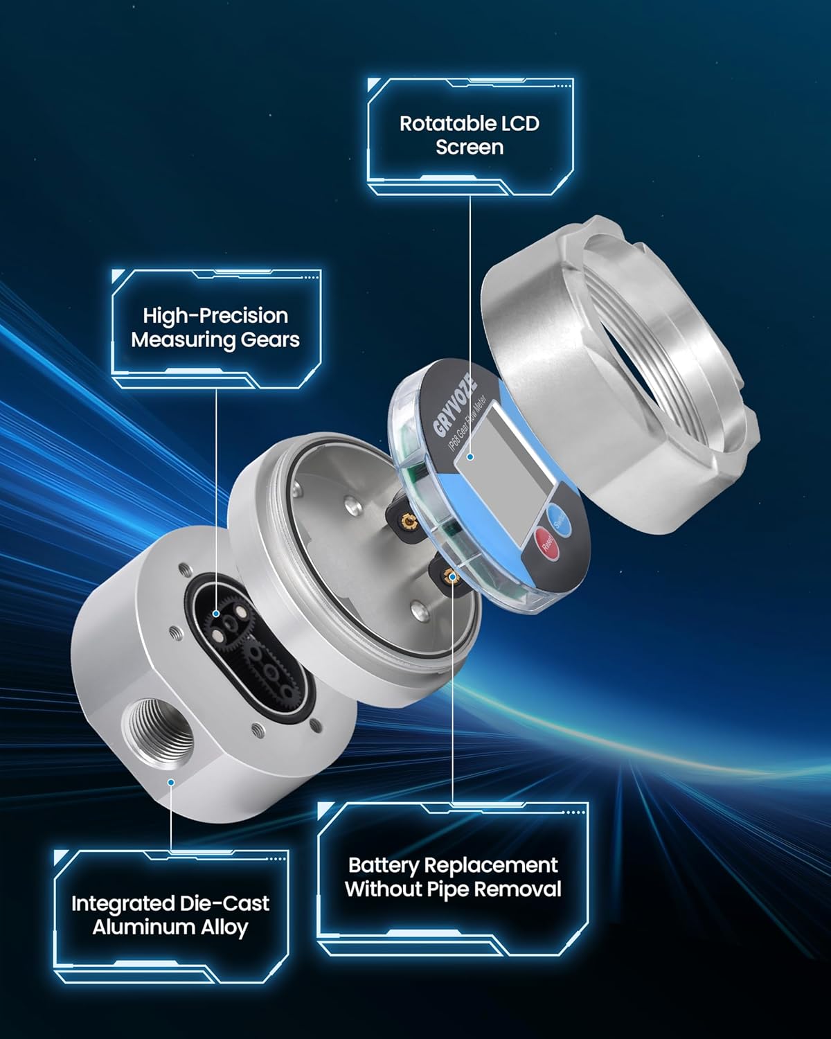
Figure 1: Internal Components of the Flow Meter. This image illustrates the meter's construction, highlighting the rotatable LCD screen, high-precision measuring gears, and the integrated die-cast aluminum alloy housing. It also shows that battery replacement is possible without pipe removal.
4. Setup and Installation
4.1 Pre-Installation Checks
- Inspect the flow meter for any visible damage.
- Ensure the piping system is clean and free of debris.
- Confirm the liquid to be measured is compatible with aluminum and the meter's internal components.
4.2 Installation Steps
- Choose Location: Select an installation point where the meter will be easily accessible for reading and maintenance. Ensure sufficient straight pipe runs upstream and downstream as recommended for accurate flow measurement.
- Depressurize System: Shut off the fluid supply and depressurize the pipeline before cutting or connecting.
- Install Meter: Connect the flow meter into the pipeline using the 1/2 inch NPT threads. Ensure the flow direction arrow on the meter body aligns with the actual fluid flow. Use appropriate thread sealant to prevent leaks.
- Secure Connections: Tighten all connections securely but do not overtighten to avoid damaging the threads or meter body.
- System Test: Slowly re-pressurize the system and check for any leaks.

Figure 2: Example of Flow Meter Installation. The meter is shown installed in a pipe, highlighting its robust design suitable for outdoor and wet conditions due to its IP68 waterproof rating.
5. Operating Instructions
5.1 Display Modes
The flow meter features a digital screen that displays three measurement modes:
- Shift Cumulative Flow: Measures the total flow for a specific operational period, which can be reset.
- Total Cumulative Flow: Measures the grand total flow, which cannot be reset by the user.
- Instantaneous Flow: Displays the current flow rate.

Figure 3: Multi-Mode Display. This image illustrates the three distinct display modes available on the flow meter: Shift Cumulative Flow, Total Cumulative Flow, and Instantaneous Flow.
5.2 Button Functions
- "Reset" Button: Used to reset the Shift Cumulative Flow. Also used for unit selection in setting mode.
- "Switch" Button: Used to cycle through display modes (Shift Cumulative, Total Cumulative, Instantaneous). Also used to enter and exit unit setting mode.
5.3 Unit Conversion
The flow meter supports four measurement units: Gallons (US gallons), Quarts (US quarts), Pints (US pints), and Liters (L). The factory default unit is Gallons.
- To enter unit setting mode, press and hold both the "Reset" and "Switch" keys simultaneously for more than 5 seconds.
- While in setting mode, press the "Reset" key to cycle through the available units (Gal, Qts, Pts, L).
- To save the selected unit and exit the setting mode, press and hold the "Switch" key for 5 seconds.

Figure 4: Unit Conversion Process. This diagram visually guides the user through changing the measurement units on the flow meter's display.
5.4 Energy Saving
The meter automatically powers off after 1 minute of inactivity to conserve battery life. It will wake up when liquid flows through it or when any button is pressed. Built-in memory retains all data even after power loss.
6. Maintenance
6.1 Cleaning
- Wipe the exterior of the meter with a soft, damp cloth. Do not use abrasive cleaners or solvents.
- Ensure the display remains clear and readable.
6.2 Battery Replacement
The flow meter is designed for easy battery replacement without disconnecting it from the pipeline.
- Depressurize System: Ensure the pipeline is depressurized and no fluid is flowing.
- Remove Front Panel: Carefully unscrew and remove the front panel of the meter where the display is located.
- Replace Batteries: Replace the old batteries with new ones, ensuring correct polarity.
- Reassemble: Securely reattach the front panel, ensuring a tight seal to maintain the IP68 rating.

Figure 5: Battery Replacement Procedure. This image illustrates the simple process of replacing the batteries by detaching the front display panel, eliminating the need to remove the entire meter from the pipeline.
7. Troubleshooting
| Problem | Possible Cause | Solution |
|---|---|---|
| No display or dim display | Low or dead batteries. | Replace batteries (refer to Section 6.2). |
| Inaccurate readings | Incorrect unit setting. Air in the system. Meter installed against flow direction. Debris in meter. | Verify unit setting (refer to Section 5.3). Purge air from the system. Reinstall meter with correct flow direction. Inspect and clean meter internals if necessary (depressurize first). |
| Leakage at connections | Improperly tightened connections. Insufficient thread sealant. Damaged threads. | Depressurize system, re-tighten connections, apply more thread sealant, or replace damaged components. |
| Meter not waking up | No fluid flow. Batteries dead. | Ensure fluid is flowing. Replace batteries. |
8. Specifications
| Parameter | Value |
|---|---|
| Model Number | A3200 |
| Connection Size | 1/2 inch NPT |
| Accuracy | ±0.5% |
| Flow Range | 0.05–6.6 GPM (0.2–25 LPM) |
| Max. Pressure | 435 psi |
| Operating Temperature | -22 °F to 158 °F (-30 °C to 70 °C) |
| Material | Aluminum |
| IP Rating | IP68 |
| Product Dimensions | 7.98 x 7.98 x 6.71 cm |
| Item Weight | 639.57 g (1.41 lbs) |
| UPC | 850072214238 |
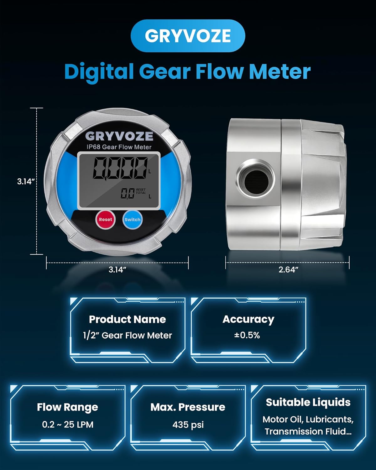
Figure 6: Product Specifications and Dimensions. This image provides a visual summary of the meter's key technical data and physical measurements.
9. Warranty and Support
9.1 Warranty Information
The GRYVOZE 1/2 inch NPT Digital Gear Flow Meter is covered by a 1-Year Manufacturer Warranty from the date of purchase. This warranty covers defects in materials and workmanship under normal use. It does not cover damage resulting from improper installation, misuse, unauthorized modification, or natural wear and tear.
9.2 Customer Support
For technical assistance, warranty claims, or any questions regarding your GRYVOZE product, please contact GRYVOZE customer support. Refer to the product packaging or the official GRYVOZE website for the most current contact information.
Manufacturer: GRYVOZE