
1. Introduction
This manual provides detailed instructions for the installation, setup, and operation of the Nutbro DL-L DMX512 to 4-Channel 0/1-10V Analog Signal LED Dimmer. This device is designed to convert DMX512 digital signals into 0/1-10V analog signals, enabling precise dimming control for compatible LED drivers and lighting systems. Please read this manual thoroughly before use to ensure proper functionality and safety.
2. Features
- Compatible with DMX512 standard protocols.
- Digital numeric screen for easy DMX decode start address setting via buttons.
- RDM (Remote Device Management) function for intercommunication between DMX master and decoder.
- Selectable 1, 2, or 4 DMX channel output.
- Configurable 0-10V or 1-10V analog output.
- Choice of logarithmic or linear dimming curve.
- Standalone RGB/RGBW mode and 4-channel dimmer mode selectable, with built-in programs controlled by buttons (independent of DMX signal).
3. Technical Specifications
| Parameter | Value |
|---|---|
| Input Voltage | 12-24 V DC or 100-240 VAC |
| Input Signal | DMX512 |
| Output Signal | 0/1-10 V Analog |
| Output Current | 4 Channels, 20mA/Channel |
| Operation Mode | Standalone, DMX |
| Current Rating | 20 Milliamps |
| Contact Type | Normally Open |
| Connector Type | Clamp |
| Switch Type | Push Button |
| Terminal | Screw |
| Material | Copper |
| Circuit Type | Parallel |
| Mounting Type | Wall Mount |
| Control Method | Push Button |
| Connectivity Protocol | DMX512 |
| Wattage | 19.2 watts |
| Control Type | Dimming |
| Compatible Devices | DMX512-compatible devices, DMX master consoles, and other DMX devices |
| Specification Met | DMX512 |
4. Product Overview

Figure 4.1: Top-down view of the Nutbro DL-L DMX512 to 4CH 0/1-10V Analog Signal LED Dimmer, showing the digital display and terminal blocks.
The Nutbro DL-L dimmer features a compact design with clearly labeled input and output terminals. A digital numeric screen on the top surface displays current settings and allows for easy configuration using adjacent push buttons. The device includes screw terminals for secure wiring connections.

Figure 4.2: Detailed view of the Nutbro DL-L dimmer, highlighting input/output terminals, digital display, and control buttons. Technical parameters and structural dimensions are also shown.
The device includes terminals for DMX IN, DMX OUT, GND, and 0/1-10V OUT (4 channels), as well as power input (AC 100-240V or DC 12-24V). The digital display provides feedback for DMX address settings and operational modes.
5. Installation
5.1 Mounting
The Nutbro DL-L dimmer is designed for wall mount installation. Ensure the mounting surface is stable and provides adequate ventilation for the device.
5.2 Wiring Diagram
Follow the wiring diagram below for correct connections. Ensure all power is disconnected before performing any wiring to prevent electrical shock.

Figure 5.1: Wiring diagram showing connections for power supply, DMX master, DMX signal amplifier, and LED drivers.
- Power Input: Connect either AC 100-240V or DC 12-24V power supply to the designated input terminals (L, N for AC; +, - for DC).
- DMX Signal: Connect the DMX master to the DMX IN terminals (D+, D-, GND). If daisy-chaining multiple decoders, connect DMX OUT of one to DMX IN of the next.
- 0/1-10V Output: Connect the 0/1-10V output terminals (OUT1-OUT4) to the corresponding 0/1-10V input of your LED drivers. Each channel supports up to 20 LED drivers.
5.3 Connection Examples
Below are examples illustrating various DMX LED lighting connection scenarios, including the use of DMX signal amplifiers for extended setups.
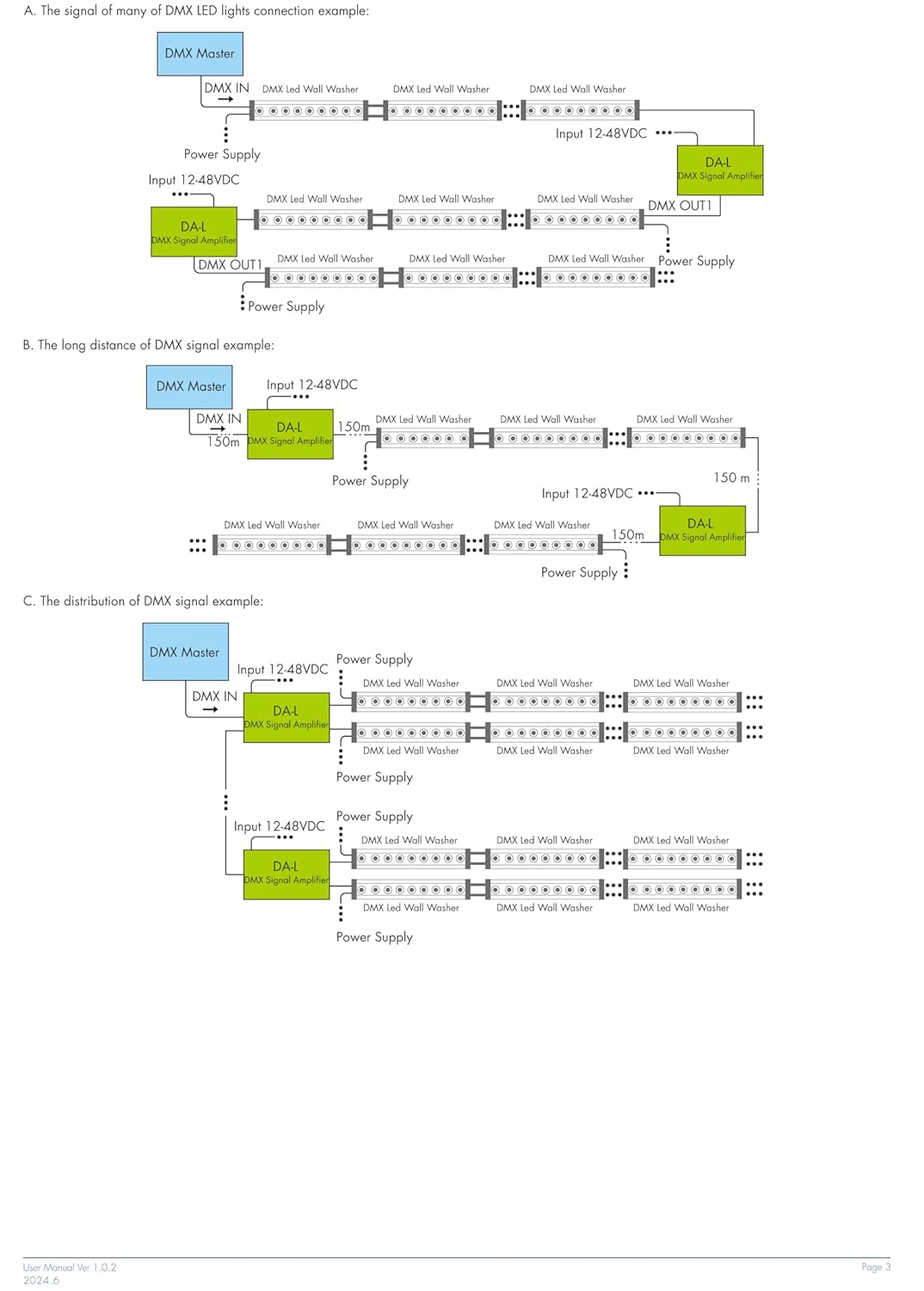
Figure 5.2: Example A - Basic DMX LED wall washer connection with a DMX signal amplifier.
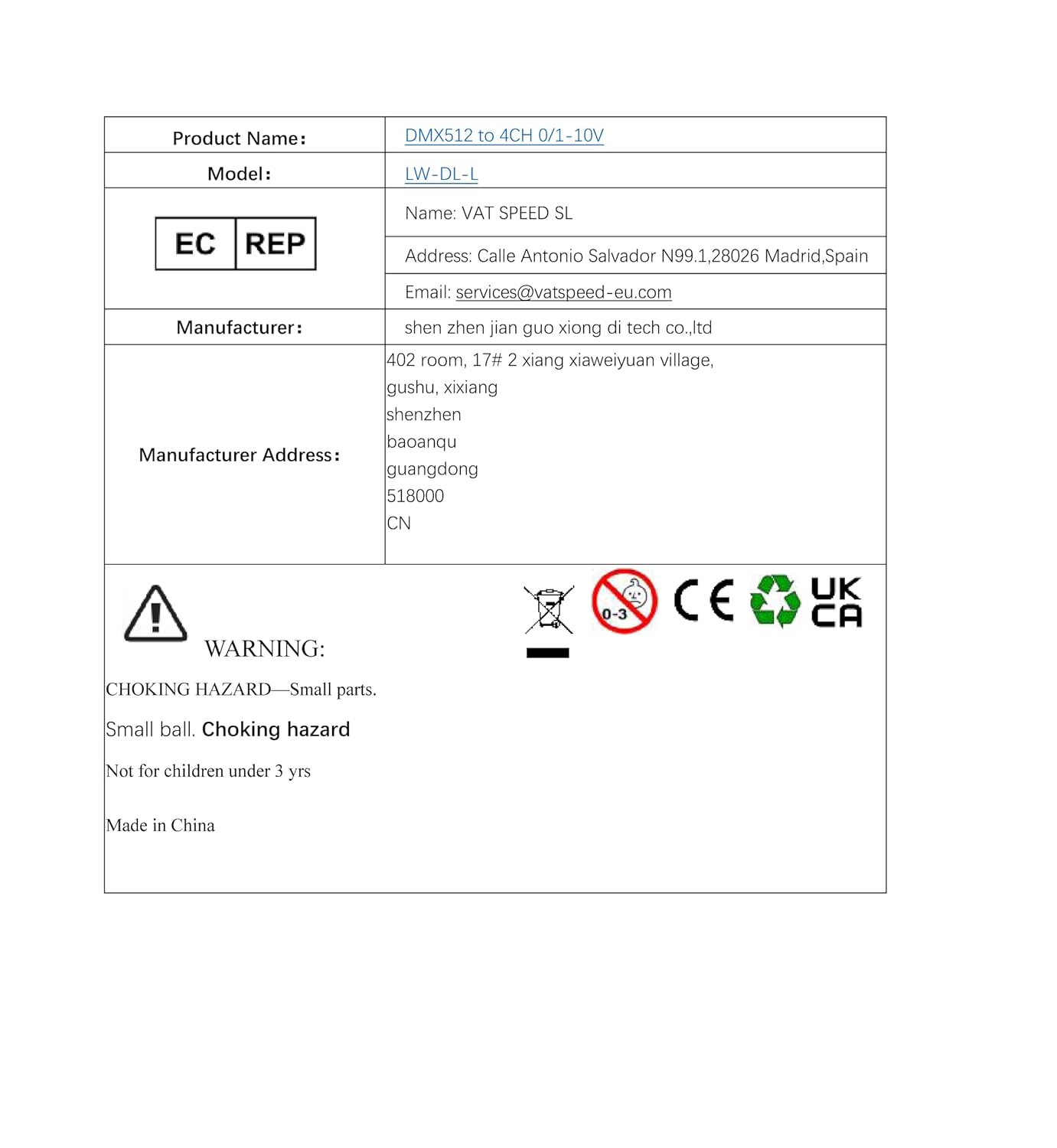
Figure 5.3: Example B - Long distance DMX signal connection using multiple amplifiers. Example C - Distribution of DMX signal with multiple amplifiers for extensive installations.
- An amplifier is recommended when more than 32 decoders are connected. Signal amplification should not exceed 5 times continuously.
- If the signal quality is poor due to longer signal lines or other issues, connect a 0.25V-90-120Ω terminal resistor at the end of the line.
- Do not exceed 20 LED drivers connected to each 0/1-10V dimmer channel.
- The maximum length of wires from the dimmer to the LED driver should not exceed 30 meters.
6. Setup and Configuration
6.1 DMX Address Setting
Use the buttons adjacent to the digital numeric screen to set the DMX decode start address. Refer to your DMX master console's manual for specific address assignment guidelines.
6.2 Output Voltage and Dimming Curve Selection
The device allows selection between 0-10V or 1-10V output and logarithmic or linear dimming curves. These settings are typically configured via the onboard buttons and digital display. Consult the device's interface for specific navigation and selection procedures.
7. Operation Modes
7.1 DMX Control Mode
In DMX control mode, the dimmer responds to DMX512 signals from a DMX master console. The dimming level of each channel is controlled by the corresponding DMX channel data.
7.2 Standalone Mode
The DL-L dimmer can operate in standalone mode without an external DMX signal. This mode offers built-in programs for RGB/RGBW control or 4-channel dimming. These programs are selected and controlled using the onboard buttons.
8. Troubleshooting
- No Dimming or Erratic Behavior:
- Verify DMX address settings match the DMX master.
- Check DMX signal cable connections for proper polarity (D+, D-, GND).
- Ensure the correct 0-10V or 1-10V output mode is selected for your LED drivers.
- If using many decoders (over 32) or long DMX lines, consider adding a DMX signal amplifier.
- For long DMX signal lines or poor signal quality, install a 0.25V-90-120Ω terminal resistor at the end of the line.
- LED Drivers Not Responding:
- Confirm power supply to both the dimmer and LED drivers.
- Check 0/1-10V wiring between the dimmer and LED drivers.
- Ensure the number of LED drivers per channel does not exceed 20.
- Verify that the wire length from the dimmer to the LED driver is not more than 30 meters.
- Device Not Powering On:
- Check power input connections (AC 100-240V or DC 12-24V).
- Ensure the power source is active and providing the correct voltage.
9. Safety Information and Warnings
WARNING:
- CHOKING HAZARD: Small parts. Not for children under 3 years.
Always disconnect power before installation or maintenance. Improper installation or use can lead to electrical shock or damage to the device and connected equipment. This product is intended for professional installation and use in accordance with local electrical codes and regulations.
10. Manufacturer Information and Support
| Product Name | DMX512 to 4CH 0/1-10V |
| Model | LW-DL-L |
| Brand | Nutbro |
| Manufacturer | FlyBoy4U (shen zhen jian guo xiong di tech co.,ltd) |
| Manufacturer Address | 402 room, 17# 2 xiang xiaweiyuan village, gushu, xixiang, shenzhen, baoanqu, guangdong, 518000, CN |
| EC Representative | VAT SPEED SL |
| EC REP Address | Calle Antonio Salvador N99 1,28026 Madrid, Spain |
| EC REP Email | services@vatspeed-eu.com |
For technical support or inquiries, please contact your local distributor or the manufacturer directly using the provided contact information.