
1. Introduction
This manual provides essential instructions for the safe and efficient operation of your POWLAND 6500W Solar Hybrid Inverter Charger. Please read this manual thoroughly before installation and use, and retain it for future reference. This device integrates a solar charge controller, inverter, and battery charger functions to offer uninterruptible power support.

Figure 1.1: POWLAND 6500W Solar Hybrid Inverter Charger. This image displays the front and side view of the white inverter unit, highlighting its compact design and integrated display panel.
2. Safety Instructions
Observe all safety warnings and precautions to prevent injury or damage to the inverter. Installation and maintenance should only be performed by qualified personnel. Ensure proper grounding and disconnect all power sources before servicing.
- Do not disassemble the unit.
- Keep away from water and flammable materials.
- Ensure adequate ventilation around the inverter.
- Use appropriate circuit breakers and wiring for all connections.
- Verify correct polarity for battery and PV connections.

Figure 2.1: Comprehensive Safety Features. This image illustrates the inverter's built-in protections, including short circuit safeguard, overcurrent defense, overvoltage protection, undervoltage prevention, overload shield, reverse charging prevention, over-temperature protection, and overcharge prevention.
3. Product Overview
3.1 Key Features
- 6500W Rated Output Power, 120Vac±5% Output Voltage Regulation.
- Integrated 120A MPPT Charge Controller.
- Supports 48V Lead Acid and LiFePO4 battery systems.
- Parallel support for up to 6 units (39kW Max) for single-phase or split-phase output (110V and 220V simultaneously).
- LCD display for monitoring all data.
- Multiple intelligent protections: PV input current/power limiting, PV input over-voltage, PV night reverse current, cooling fans.
- Overload, over-temperature, and short circuit protection.
- Automatic restart when AC power is restored.
- WiFi port for remote monitoring (requires additional WiFi device).
3.2 Components
The inverter unit includes the main power conversion module, an integrated MPPT charge controller, and a user interface display. Connection terminals are provided for AC input/output, battery, and PV array.
4. Setup
4.1 Installation Location
Install the inverter in a well-ventilated area, away from direct sunlight, heat sources, and moisture. Ensure sufficient clearance around the unit for proper airflow.
4.2 Wiring Connections
Refer to the connection diagram for proper wiring. All connections must be secure and comply with local electrical codes. The inverter requires connection to a 48V battery system and solar panels. It can also connect to mains power or a generator.
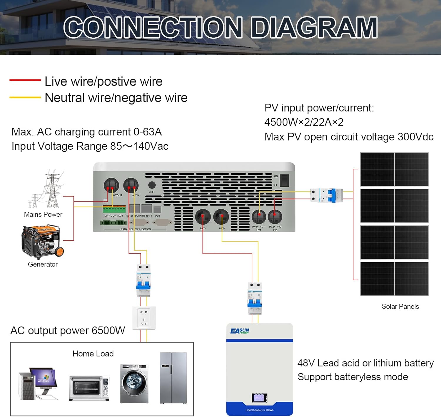
Figure 4.1: Connection Diagram. This diagram illustrates the wiring for the POWLAND inverter, showing connections for solar panels, 48V battery (lead acid or lithium), mains power/generator, and home loads. It highlights live/positive (red) and neutral/negative (yellow) wires.
4.3 Battery Compatibility
The inverter is compatible with 48V Lead Acid (SLD, FLD, AGM, GEL) and LiFePO4 batteries. It supports batteryless mode and features an activation function for dormant lithium batteries, triggered by utility or photovoltaic access.

Figure 4.2: Battery Compatibility. This image shows the inverter's compatibility with various 48V battery types, including SLD, FLD, AGM, GEL, and LI (Lithium). It also notes support for batteryless mode and battery activation features.
4.4 Parallel Operation
The inverter supports parallel operation of up to 6 units, achieving a maximum output of 39kW. This configuration allows for both single-phase and split-phase output (110V and 220V simultaneously).

Figure 4.3: Parallel Support. This image illustrates how multiple POWLAND inverters can be connected in parallel for increased output, showing configurations for 2, 3, and 6 inverters in a single-phase setup, reaching up to 39000W output.
5. Operating Instructions
5.1 Powering On/Off
After all connections are verified, switch on the battery breaker, then the PV array breaker, and finally the inverter's power switch. To power off, reverse the sequence.
5.2 LCD Display and Settings
The LCD display provides real-time monitoring of system status, input/output voltages, current, power, and battery charge level. Use the navigation buttons to access and adjust various operating parameters.
Video 5.1: Hybrid Solar Inverter Display. This video demonstrates the functionality and display interface of a hybrid solar inverter, showing various operational parameters and settings.
5.3 Charging and Output Modes
The inverter offers four charging modes (Mains First, Solar First, Hybrid Charge, Only Solar) and four output modes (Solar First, Mains First, Inverter First, Hybrid Output) to optimize energy usage based on your preferences and available power sources.

Figure 5.1: Easy-to-Use Sectional Charging and Discharging. This image illustrates the four charging modes (Mains First, Solar First, Hybrid Charge, Only Solar) and four output modes (Solar First, Mains First, Inverter First, Hybrid Output) available on the POWLAND inverter.
6. Maintenance
Regular maintenance ensures optimal performance and longevity of your inverter. Perform the following checks periodically:
- Clean Vents: Ensure cooling vents are free from dust and debris.
- Check Connections: Verify all electrical connections are tight and free from corrosion.
- Inspect Wiring: Look for any signs of wear, damage, or overheating in the wiring.
- Monitor Performance: Regularly check the LCD display for any error codes or unusual readings.
- Battery Health: For lead-acid batteries, check electrolyte levels and specific gravity as per battery manufacturer guidelines.
7. Troubleshooting
If you encounter issues with your inverter, refer to the following common troubleshooting steps:
| Problem | Possible Cause | Solution |
|---|---|---|
| No output power | Inverter off, battery low, input power issue | Check power switch, charge battery, verify AC/PV input. |
| Overload error | Connected load exceeds inverter capacity | Reduce connected load or disconnect non-essential appliances. |
| Battery not charging | PV input too low, battery connection issue, MPPT controller fault | Check solar panel output, battery wiring, and MPPT settings. |
| High temperature warning | Insufficient ventilation, blocked fan, excessive ambient temperature | Ensure clear airflow, clean fans, relocate if necessary. |
8. Specifications
Below are the technical specifications for the POWLAND 6500W Solar Hybrid Inverter Charger:
| Feature | Specification |
|---|---|
| Brand | POWLAND |
| Model Name | 6500W |
| Rated Output Power | 6500 Watts |
| Peak Output Power | 7150 Watts |
| Output Voltage | 120 Volts (AC) |
| Electrical Output Waveform | Pure Sine Wave |
| Input Voltage | 48 Volts (DC) |
| Max PV Array Open Circuit Voltage | 300VDC |
| PV Operating Voltage Range | 120-300Vdc |
| MPPT Voltage Range | 90-260Vdc |
| Max AC Input Voltage | 140Vac |
| Max PV Input Current | 22A |
| Max Charging Current (AC+DC) | 120A |
| Recommended Uses | Backup Power, Off-Grid Living, Powering Tools and Equipment, Solar Energy Systems |
| Power Source Type | Solar Powered |
| Parcel Dimensions | 68 x 47 x 22 cm; 21.12 kg |
Video 8.1: MPPT Solar Charge Controller Test. This video demonstrates the testing of an 80A MPPT solar charge controller, showing its performance and efficiency in a controlled environment.
Video 8.2: 80A Solar Charge Controller Overview. This video provides a visual overview of an 80A solar charge controller, showcasing its design and features.
9. Warranty and Support
POWLAND provides technical support for this product. For warranty claims or technical assistance, please contact the seller or manufacturer directly. Ensure you have your purchase details and model number available when seeking support.
- Manufacturer: Shenzhen Bentuo Electronic Technology Co., Ltd.
- Contact: Refer to your purchase documentation for specific support channels.