
BSIDE S500
BSIDE S500 Digital Multimeter User Manual
Model: S500
1. Introduction
The BSIDE S500 is a compact, high-precision digital multimeter designed for electrical measurements in various applications. It features a 20000-count display, True RMS capability, and a graphic display mode for data recording. This manual provides essential information for the safe and effective use of your BSIDE S500 multimeter.

Image 1.1: The BSIDE S500 Digital Multimeter with its included accessories, including test leads, a charging cable, and a protective carrying case.
2. What's in the Box
Carefully unpack the contents and verify that all items are present and undamaged:
- BSIDE S500 Digital Multimeter
- Test Leads (Red and Black)
- USB Charging Cable
- K-Type Thermocouple
- User Manual (English)
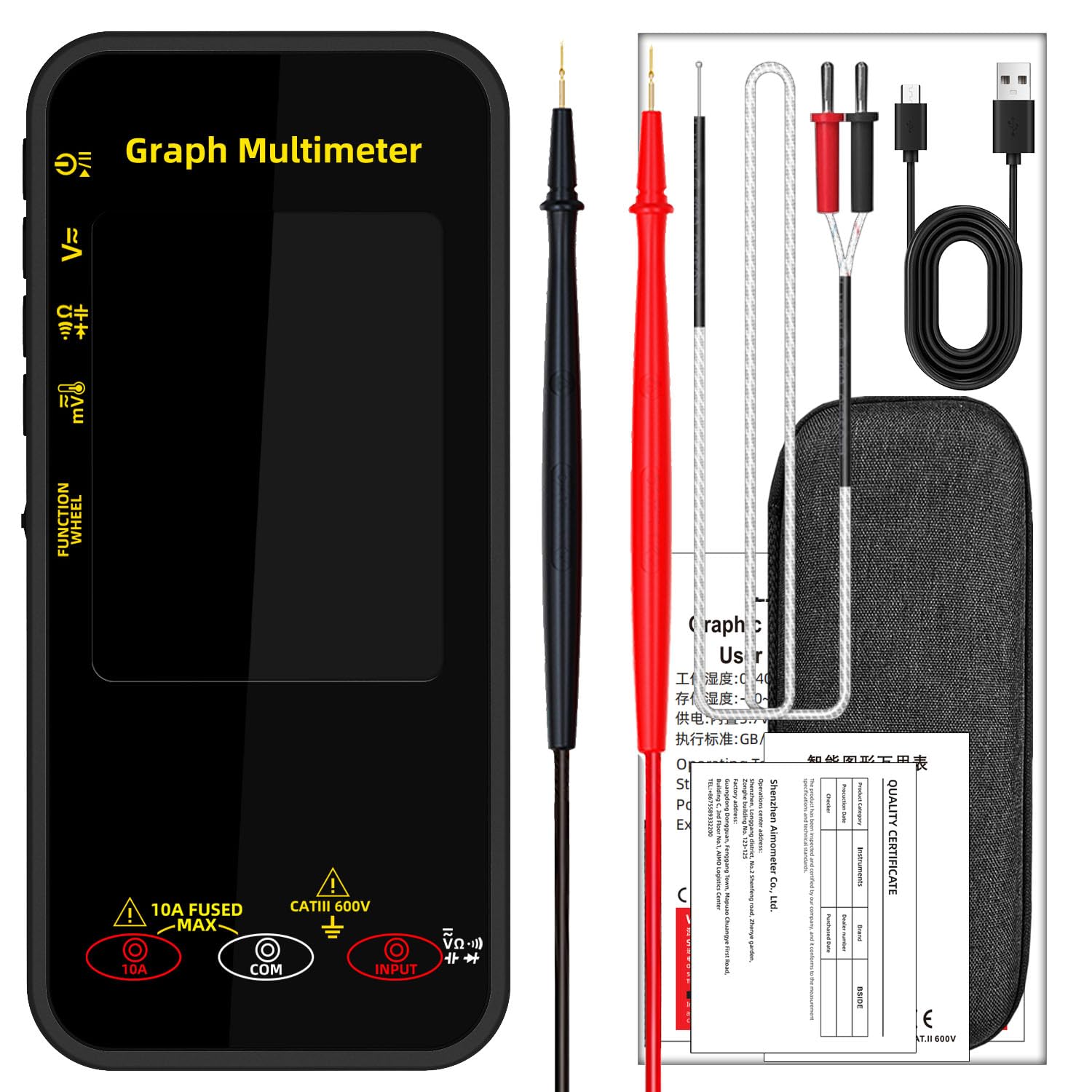
Image 2.1: All components included with the BSIDE S500 Multimeter, neatly arranged.
3. Product Features
- Dual Mode Operation: Offers both digital and recording modes for all test functions, allowing for real-time value display and historical data tracking.
- High Precision Measurements: Measures AC/DC current (up to 10A), DC voltage (up to 1000V), AC voltage (up to 750V), resistance, continuity, millivolts (0-200mV), capacitance, diode, and temperature. Includes peak voltage measurements.
- Large Color Display: Features a 3.2-inch color LCD with clear, bright readings. The display supports automatic rotation between horizontal and vertical orientations, similar to a smartphone, and can be locked.
- Compact and Portable: Its mini size (14.3 x 6.6 x 2.1 cm) makes it easy to carry and store.
- Intuitive Controls: Functions can be selected using either buttons or the function wheel, or a combination of both.
- Rechargeable Battery: Integrated 3.7V rechargeable battery for extended use.
- Data Hold Function: Allows for freezing the displayed measurement.
- Auto-Ranging and Anti-Burn Protection: Enhances safety and ease of use.
- Protective Case: Supplied with a high-quality EVA case for durability and transport.

Image 3.1: The multimeter's display is designed for clear visibility from various angles.

Image 3.2: The multimeter is shown with its durable protective case.
4. Safety Information
To ensure safe operation and avoid personal injury or damage to the multimeter, please read and follow all safety instructions carefully:
- Always ensure the multimeter is in the correct function mode before connecting test leads to a circuit.
- Do not apply voltage or current that exceeds the maximum specified limits for the multimeter.
- Exercise extreme caution when working with live circuits. High voltages can be dangerous.
- Inspect test leads for damage (e.g., cracked insulation, exposed metal) before each use. Replace damaged leads immediately.
- Do not use the multimeter if it appears damaged or is not operating correctly.
- Ensure your hands are dry when making measurements.
- Always connect the common (COM) test lead first and disconnect it last.
- Do not operate the multimeter in explosive atmospheres or in the presence of flammable gases or dust.
- Refer to the specifications section for detailed input limits.
5. Setup
5.1. Charging the Battery
The BSIDE S500 is powered by an internal rechargeable 3.7V lithium-ion battery. Before first use, or when the battery indicator shows low charge, connect the multimeter to a USB power source using the provided USB charging cable.
- Connect the small end of the USB cable to the charging port on the multimeter.
- Connect the standard USB end to a USB wall adapter, computer USB port, or power bank.
- The charging indicator on the display will show the charging status.
5.2. Connecting Test Leads
The test leads are essential for making electrical measurements. Always ensure they are securely connected.
- Insert the black test lead into the COM (Common) input jack.
- Insert the red test lead into the INPUT jack for voltage, resistance, capacitance, diode, and temperature measurements.
- For current measurements (up to 10A), insert the red test lead into the 10A FUSED MAX jack.
6. Operating Instructions
6.1. Power On/Off
Press and hold the power button (usually marked with a power symbol) to turn the multimeter on or off.
6.2. Function Selection
The BSIDE S500 features a function wheel and/or buttons for selecting measurement modes. Rotate the function wheel or press the designated function buttons to cycle through available measurement types (e.g., Voltage, Current, Resistance, Capacitance, Diode, Continuity, Temperature).

Image 6.1: The multimeter in use, showing an AC voltage measurement on its display.
6.3. Automatic Screen Rotation
The display automatically adjusts its orientation (portrait or landscape) based on how the device is held. This feature can be locked if a fixed orientation is preferred.

Image 6.2: The multimeter's display can rotate 360 degrees for optimal viewing.
6.4. Measurement Modes
Below are common measurement procedures:
- DC/AC Voltage Measurement (V):
- Select the DC V or AC V function.
- Connect the red test lead to the positive side of the circuit and the black test lead to the negative side (for DC) or across the points to be measured (for AC).
- Read the voltage value on the display.
- DC/AC Current Measurement (A):
- IMPORTANT: Ensure the red test lead is in the 10A FUSED MAX jack.
- Select the DC A or AC A function.
- Open the circuit where current is to be measured and connect the multimeter in series.
- Read the current value on the display.
- Resistance Measurement (Ω):
- Ensure the circuit is de-energized before measuring resistance.
- Select the Resistance (Ω) function.
- Connect the test leads across the component to be measured.
- Read the resistance value.
- Continuity Test:
- Ensure the circuit is de-energized.
- Select the Continuity function (often indicated by a speaker symbol).
- Connect the test leads across the circuit or component. A continuous beep indicates continuity.
- Diode Test:
- Ensure the circuit is de-energized.
- Select the Diode function.
- Connect the red lead to the anode and the black lead to the cathode of the diode. The display will show the forward voltage drop. Reverse the leads to check for open circuit.
- Capacitance Measurement (F):
- Ensure the capacitor is fully discharged before measurement.
- Select the Capacitance (F) function.
- Connect the test leads across the capacitor.
- Read the capacitance value.
- Temperature Measurement (°C/°F):
- Select the Temperature function.
- Connect the K-type thermocouple to the appropriate input jacks (usually marked for temperature).
- Place the thermocouple tip on or near the object whose temperature is to be measured.
- Read the temperature value.
6.5. Data Recording (Graph Mode)
The BSIDE S500 can display measurements graphically, allowing you to observe trends over time.
- In a measurement mode, activate the recording function (refer to the on-screen prompts or specific button for this feature).
- The display will switch to a graph view, showing the measured values plotted over time.
- This mode is useful for monitoring fluctuating signals or identifying intermittent issues.
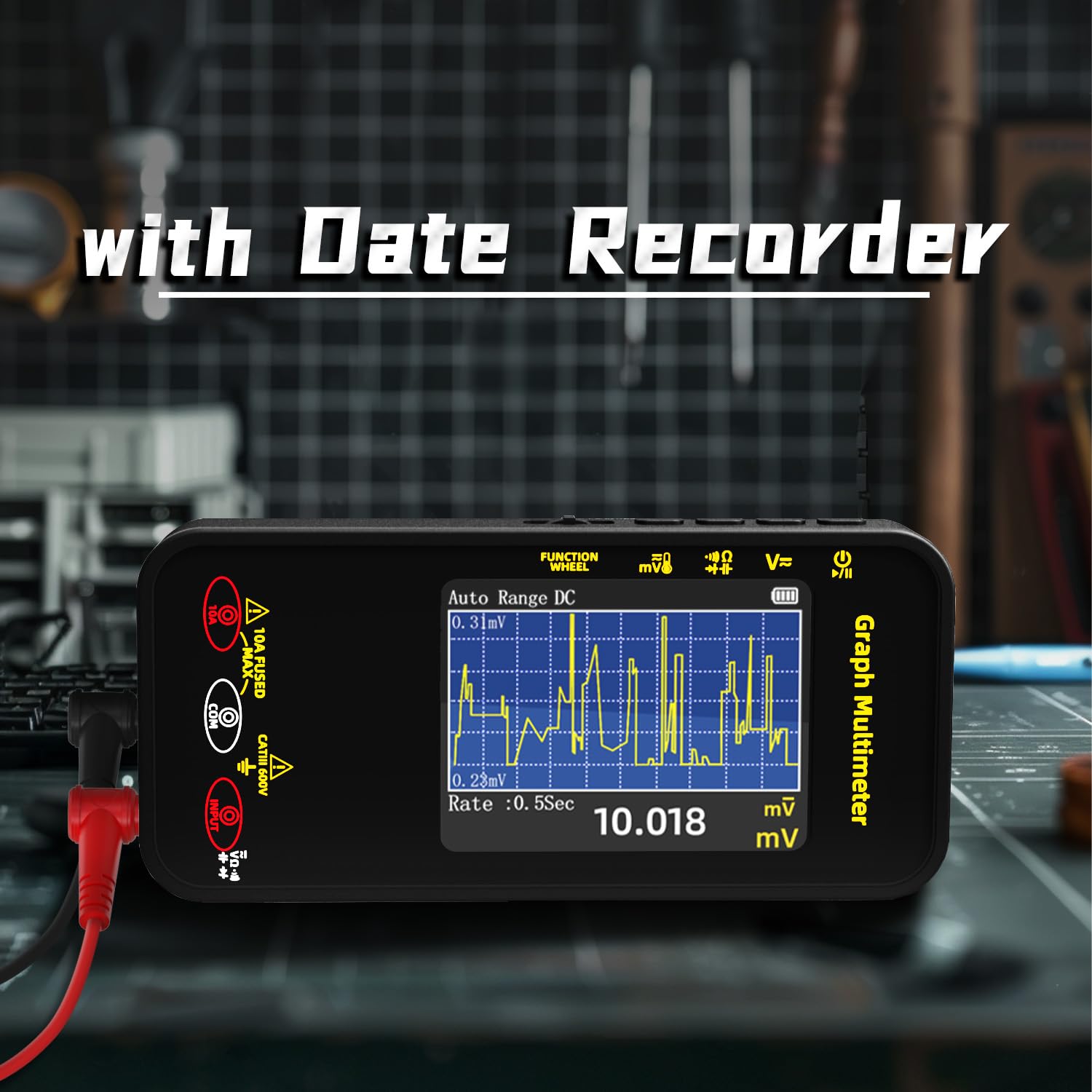
Image 6.3: The multimeter's display in data recording mode, showing a graphical representation of measurements over time.

Image 6.4: The multimeter's 20000-count display provides high resolution for precise readings.
7. Maintenance
7.1. Cleaning
To clean the multimeter, wipe the case with a damp cloth and a mild detergent. Do not use abrasives or solvents. Ensure the device is powered off and disconnected from any circuits before cleaning.
7.2. Battery Care
Recharge the internal battery regularly, especially if the multimeter will not be used for an extended period. Avoid fully discharging the battery frequently to prolong its lifespan.
7.3. Storage
When not in use, store the multimeter and its accessories in the provided protective case in a cool, dry place, away from direct sunlight and extreme temperatures.
8. Troubleshooting
- No Display/Power:
- Check if the battery is charged. Connect to a USB charger.
- Ensure the power button is pressed and held sufficiently to turn on the device.
- Incorrect Readings:
- Verify that the correct function mode is selected for the measurement.
- Ensure test leads are correctly and securely inserted into the appropriate jacks.
- Check test leads for damage or poor connection.
- Ensure the circuit under test is properly prepared (e.g., de-energized for resistance).
- Fuse Blown (for Current Measurement):
- If current measurements are not working, the internal fuse for the 10A input may have blown due to overcurrent. Fuse replacement should only be performed by qualified personnel.
9. Specifications
| Parameter | Specification |
|---|---|
| Display | 20000 Counts, 3.2-inch Color LCD |
| DC Voltage (mV) | 20.000mV/200.00mV, Resolution: 0.001mV/0.01mV, Accuracy: ±(0.1%+3) |
| DC Voltage | 2.0000V/20.000V/200.00V/1000V, Resolution: 0.0001V/0.001V/0.01V/0.1V, Accuracy: ±(0.1%+3) |
| AC Voltage (mV) | 20.000mV/200.00mV, Resolution: 0.001mV/0.01mV, Accuracy: ±(0.5%+3) |
| AC Voltage | 2.0000V/20.000V/200.00V/750V, Resolution: 0.0001V/0.001V/0.01V/0.1V, Accuracy: ±(0.5%+3) |
| DC Current | 2.0000A/10.000A, Resolution: 0.0001A/0.001A, Accuracy: ±(0.8%+3) |
| AC Current | 2.0000A/10.000A, Resolution: 0.0001A/0.001A, Accuracy: ±(0.8%+3) |
| Resistance | 0.01Ω-200MΩ, Resolution: 0.01Ω, Accuracy: ±(0.5%+3) |
| Capacitance | 0.01nF-99.999mF, Resolution: 0.01nF, Accuracy: ±(2.0%+5) |
| Temperature | -20°C ~ 1300°C / -4°F ~ 2372°F, Resolution: 1°C/1°F, Accuracy: ±(2.0%+5) |
| Diode Test | Yes |
| Continuity Test | Yes |
| Power Supply | 3.7V Rechargeable Battery |
| Dimensions | 143 x 66.6 x 21.1 mm |
| Weight | 159.5 g |
10. Warranty and Support
For warranty information and technical support, please refer to the documentation provided with your purchase or contact BSIDE customer service. This product includes a user manual in English, and a PDF version in Italian is available via email.
Related documentsS500


Ask a question about this manual
Ask about setup, troubleshooting, compatibility, parts, safety, or missing instructions. Manuals+ will review the question and use this page’s manual context to help answer it.