1. Introduction
This manual provides detailed instructions for the installation, operation, and maintenance of the Planet IGS-4215-8P2T2S Industrial Managed Switch. This device is designed for robust industrial networking environments, offering high-speed data transmission and Power over Ethernet (PoE+) capabilities. Please read this manual thoroughly before using the product to ensure proper setup and optimal performance.
2. Product Overview
2.1 Key Features
- Eight 10/100/1000BASE-T Gigabit Ethernet RJ45 ports with IEEE 802.3at/af PoE+ Injector function (Ports 1 to 8).
- Two 10/100/1000BASE-T Gigabit Ethernet RJ45 ports (Ports 9 to 10).
- Two 100/1000BASE-X mini-GBIC/SFP slots for SFP type auto detection (Ports 11 to 12).
- One RJ45 console interface for basic management and setup.
- Complies with IEEE 802.3at Power over Ethernet Plus, end-span PSE.
- Backward compatible with IEEE 802.3af Power over Ethernet.
- Supports up to 8 ports of IEEE 802.3af/802.3at devices powered.
- 240-watt PoE budget.
- Supports PoE power up to 36 watts for each PoE port.
- PoE management features including total PoE power budget control and per-port PoE function enable/disable.
2.2 Physical Components
The IGS-4215-8P2T2S switch features a robust industrial design with various ports and indicators for easy deployment and monitoring.
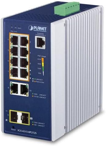
Figure 2.1: Angled view of the Planet IGS-4215-8P2T2S Industrial Managed Switch, showing the front panel with ports and indicators, and the side heat sink.
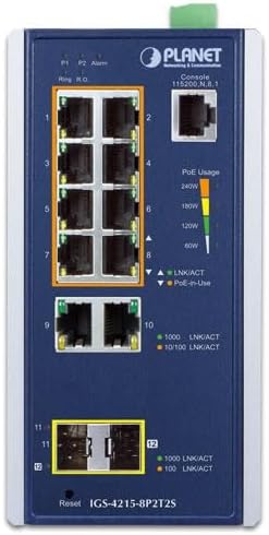
Figure 2.2: Front panel of the IGS-4215-8P2T2S switch. This view highlights the eight PoE+ RJ45 ports (1-8), two standard RJ45 ports (9-10), two SFP slots (11-12), console port, reset button, and LED indicators for power, alarm, link/activity, and PoE usage.
- PoE+ RJ45 Ports (1-8): Connect PoE-powered devices (PDs) such as IP cameras, VoIP phones, or wireless access points.
- Standard RJ45 Ports (9-10): Connect non-PoE network devices or uplink to other switches/routers.
- SFP Slots (11-12): Insert 100/1000BASE-X SFP transceivers for fiber optic connections, extending network reach.
- Console Port: RJ45 port for command-line interface (CLI) management.
- Reset Button: Used to restore factory default settings.
- LED Indicators: Provide visual status for power, alarm, link/activity, and PoE usage.

Figure 2.3: Rear panel of the IGS-4215-8P2T2S switch, showing the DC power input terminal block and fault alarm loading connections. The power input supports 48-54V DC, 6A max.
- DC Power Input: Terminal block for connecting 48-54V DC power supply.
- Fault Alarm Loading: Terminal block for connecting external alarm systems.
3. Setup
3.1 Unpacking
Carefully unpack the switch and verify that all components are present and undamaged. Retain the packaging materials for future transport or storage.
3.2 Mounting
The IGS-4215-8P2T2S is designed for industrial environments and typically supports DIN-rail or wall mounting. Refer to the specific mounting kit instructions for secure installation in your desired location. Ensure adequate ventilation around the device.
3.3 Power Connection
- Ensure the power source is off before connecting.
- Connect a 48-54V DC power supply to the terminal block on the rear panel (refer to Figure 2.3). Observe correct polarity (V1+, V1-, V2+, V2-).
- Secure the wires firmly within the terminal block.
- Once all network connections are made, apply power to the switch.
3.4 Network Connections
- RJ45 Ports: Connect standard Ethernet cables (Cat5e or higher) from your network devices to the RJ45 ports (1-10). For PoE-powered devices, use ports 1-8.
- SFP Slots: Insert compatible 100/1000BASE-X SFP transceivers into slots 11-12, then connect fiber optic cables.
- Console Port: For initial configuration or advanced management, connect a console cable from your computer to the RJ45 console port.
4. Operating Instructions
4.1 Power On and Initial Status
Upon applying power, the switch will initiate its boot sequence. Observe the power LED for a steady green indication. Link/Activity LEDs for connected ports will illuminate when a valid network connection is established and blink during data transmission. PoE-in-Use LEDs will indicate when power is being supplied to a connected PD.
4.2 Power over Ethernet (PoE+) Functionality
The IGS-4215-8P2T2S supports IEEE 802.3at/af PoE+ on ports 1-8, providing up to 36 watts per port with a total budget of 240 watts. The switch automatically detects and powers compatible PDs. The PoE Usage LEDs provide a visual indication of the total power consumption.
4.3 Management
As a managed switch, the IGS-4215-8P2T2S offers various management options:
- Web-based Management: Access the switch's graphical user interface (GUI) via a web browser for easy configuration and monitoring. Refer to the full user manual for default IP address and login credentials.
- Command Line Interface (CLI): Use the console port for text-based configuration, ideal for advanced users and scripting.
- SNMP: Integrate the switch into network management systems using SNMP for centralized monitoring.
5. Maintenance
5.1 Cleaning
Periodically clean the exterior of the switch with a soft, dry cloth. Do not use liquid or aerosol cleaners. Ensure ventilation openings are free from dust and debris to prevent overheating.
5.2 Firmware Updates
Regularly check the manufacturer's website for firmware updates. Keeping the firmware up-to-date ensures optimal performance, security, and access to new features. Follow the provided instructions carefully when performing firmware upgrades.
5.3 Environmental Considerations
Ensure the switch operates within its specified temperature and humidity ranges. Avoid exposing the device to direct sunlight, excessive heat, moisture, or strong electromagnetic fields.
6. Troubleshooting
6.1 No Power
- Verify the DC power supply is correctly connected and providing the specified voltage (48-54V DC).
- Check the power source and ensure it is active.
- Confirm the power LED on the switch is illuminated.
6.2 No Link/Activity
- Ensure network cables are securely connected to both the switch and the connected device.
- Verify the cable type and length are appropriate for the connection speed.
- Check the status of the connected device.
- Try a different port or cable.
6.3 PoE Not Functioning
- Ensure the connected device is a PoE-powered device (PD) and complies with IEEE 802.3af/at standards.
- Verify the PD's power requirements do not exceed 36 watts per port or the total 240-watt budget.
- Check the PoE-in-Use LED for the specific port.
- Access the switch's management interface to check PoE settings and ensure the port's PoE function is enabled.
6.4 Factory Reset
If issues persist or configuration problems arise, a factory reset can restore the switch to its default settings. Locate the reset button on the front panel (refer to Figure 2.2) and press and hold it for approximately 5-10 seconds until the system LEDs indicate a reset sequence.
7. Specifications
| Feature | Description |
|---|---|
| Model | IGS-4215-8P2T2S |
| Ethernet Ports | 8x 10/100/1000BASE-T RJ45 (PoE+), 2x 10/100/1000BASE-T RJ45 |
| SFP Slots | 2x 100/1000BASE-X mini-GBIC/SFP |
| Console Interface | 1x RJ45 |
| PoE Standard | IEEE 802.3at/af |
| PoE Power Output | Up to 36W per port (Ports 1-8) |
| Total PoE Budget | 240 Watts |
| DC Power Input | 48-54V DC, 6A max |
| Item Weight | 5 pounds |
| Included Components | Managed Switch |
8. Warranty and Support
This Planet IGS-4215-8P2T2S Industrial Managed Switch comes with a standard manufacturer's warranty. For specific warranty terms, duration, and conditions, please refer to the warranty card included with your product or visit the official Planet Technology website. For technical support, troubleshooting assistance, or service inquiries, please contact Planet Technology customer support directly. Keep your purchase receipt and product serial number readily available when seeking support.


