1. Introduction
This manual provides essential information for the safe and efficient operation of your VAR TECH Programmable DC Power Supply, model PPS-3020 S. Please read this manual thoroughly before using the device to ensure proper functionality and to prevent damage or injury.
1.1 Safety Precautions
- Always connect the power supply to a grounded outlet.
- Do not operate the device in wet or damp conditions.
- Ensure proper ventilation to prevent overheating.
- Do not open the casing; refer servicing to qualified personnel.
- Verify correct voltage and current settings before connecting to a load.
2. Product Overview
The VAR TECH PPS-3020 S is a programmable DC power supply offering 0-30V and 0-20A output with a USB interface for remote control. It features high precision, stability, and multiple protection functions.
2.1 Key Features
- 0-30 V, 0-20 A Programmable output with USB Interface.
- 5 L.E.D. Multicolour meters of 4 Digits for CV (Constant Voltage) and CC (Constant Current) indication.
- 6 Sets of Memory for storing and recalling settings.
- Output On/Off Facility for safe load connection/disconnection.
- Supports MODBUS-RTU Commands for remote control.
- Over Voltage Protection (OVP), Over Current Protection (OCP), and Over Temperature Protection (OTP).
2.2 Front Panel Controls and Indicators

Figure 1: Front Panel Layout
- Digital Displays: Multi-color LED displays for Voltage (V), Current (A), Power (W), and Set Values (V-SET, I-SET).
- CV/CC Indicators: LEDs indicating Constant Voltage or Constant Current mode.
- V-SET Button: Press to adjust voltage setting.
- I-SET Button: Press to adjust current setting.
- ADJUST Knob: Rotary encoder for fine adjustment of voltage and current values.
- MEMORY Button: Access memory functions.
- LIST Button: Navigate through memory slots.
- ON / OFF Button: Toggles output power.
- LEFT / RIGHT Buttons: Used for digit selection during setting adjustments.
- USB Port: For PC connection and remote control.
- Power Switch: Main power ON/OFF button.
- Output Terminals: Positive (+), Negative (-), and Ground (GND) terminals for load connection.
2.3 Side and Rear Panel
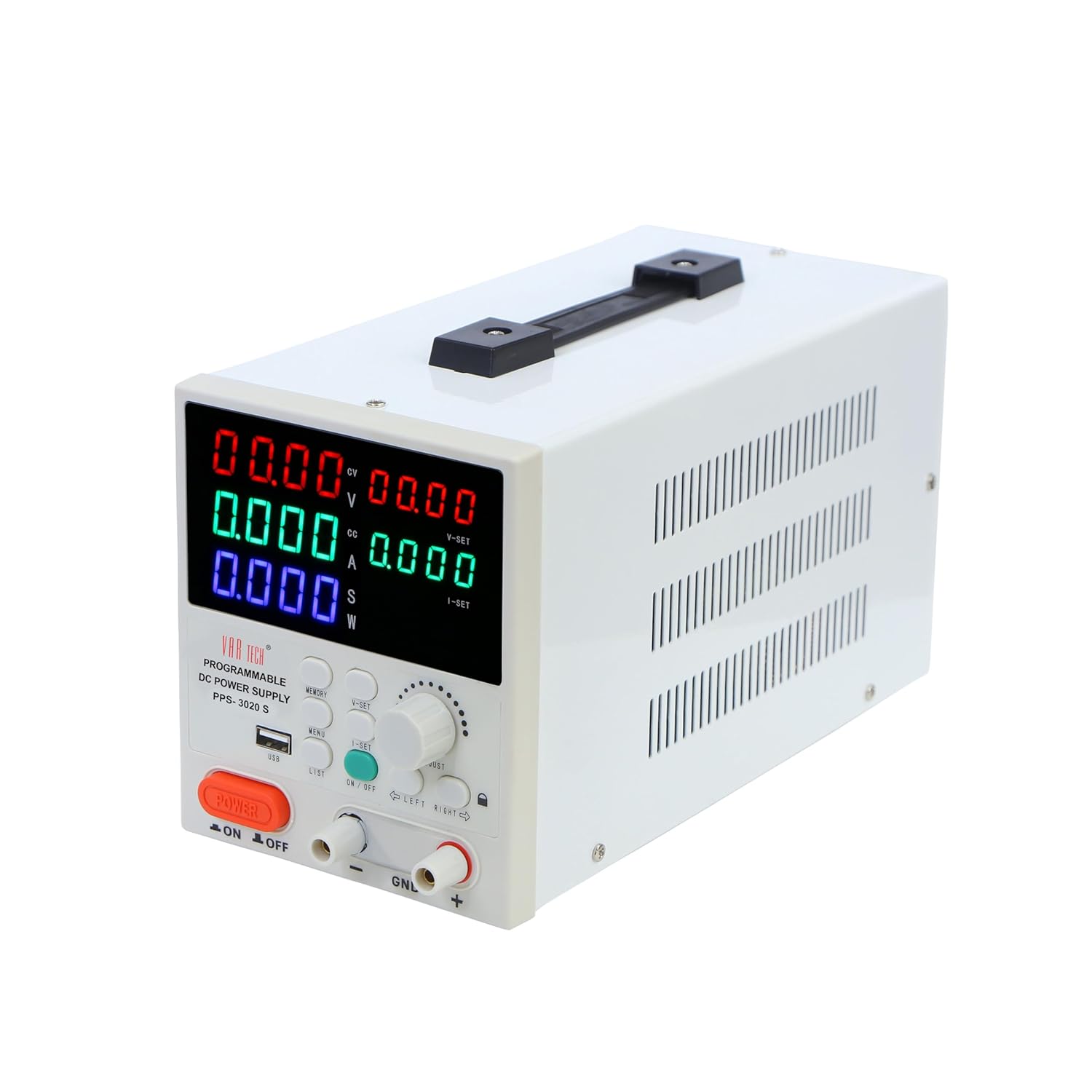
Figure 2: Angled View with Side Vents
The side panels feature ventilation grilles for heat dissipation. The rear panel typically includes the AC power input socket, a cooling fan, and potentially additional communication ports (not explicitly shown in provided images but common for such devices).
3. Setup
3.1 Unpacking and Inspection
Carefully remove the power supply from its packaging. Inspect the unit for any signs of physical damage. Retain the packaging for future transport or storage.
3.2 Power Connection
- Ensure the main power switch on the front panel is in the OFF position.
- Connect the provided AC power cord to the power input socket on the rear panel of the power supply.
- Plug the other end of the AC power cord into a suitable grounded electrical outlet.
3.3 Output Terminal Connection
Connect your load to the output terminals using appropriate test leads. Ensure correct polarity:
- Connect the positive (+) terminal of the power supply to the positive input of your load.
- Connect the negative (-) terminal of the power supply to the negative input of your load.
- The GND terminal is for chassis ground and should be connected to the load's ground if required for safety or noise reduction.
Caution: Do not short-circuit the output terminals for extended periods, even with protection enabled.
4. Operating Instructions
4.1 Power On/Off
- Press the main POWER ON/OFF switch on the front panel to turn the unit on. The displays will illuminate.
- To turn off, press the POWER ON/OFF switch again.
4.2 Setting Voltage and Current
- Press the V-SET button to enter voltage setting mode. The voltage display will flash.
- Use the ADJUST knob to change the voltage value. Turn clockwise to increase, counter-clockwise to decrease.
- Use the LEFT and RIGHT buttons to select the digit you wish to adjust for finer control.
- Press V-SET again to confirm the setting or wait a few seconds for it to auto-confirm.
- Repeat steps 1-4 for current setting using the I-SET button.
4.3 Output Control
After setting the desired voltage and current, press the ON / OFF button (typically green) to enable or disable the output. When the output is ON, the corresponding indicator will light up, and power will be supplied to the load. When OFF, no power is supplied.
4.4 Memory Functions
The PPS-3020 S allows you to store and recall up to 6 sets of voltage and current settings.
- To Save: Set the desired voltage and current. Press and hold the MEMORY button until a memory slot number (e.g., 'M1') flashes on the display. Use the ADJUST knob or LIST button to select a memory slot (M1-M6), then press MEMORY again to save.
- To Recall: Press the MEMORY button briefly. The current memory slot will be displayed. Use the ADJUST knob or LIST button to select the desired memory slot. Press MEMORY again to load the stored settings.
4.5 USB Interface and MODBUS-RTU
The USB port on the front panel allows connection to a computer for remote control and monitoring. The device supports MODBUS-RTU commands, enabling integration into automated test systems or custom software applications. Refer to the separate software manual or communication protocol guide for detailed instructions on using the USB interface and MODBUS-RTU commands.
5. Maintenance
5.1 Cleaning
To clean the unit, disconnect it from the power source. Use a soft, dry cloth to wipe the exterior. Do not use abrasive cleaners or solvents. Ensure no liquids enter the device.
5.2 Storage
When not in use for extended periods, store the power supply in a cool, dry environment, away from direct sunlight and excessive dust. It is recommended to use the original packaging for storage.
6. Troubleshooting
| Problem | Possible Cause | Solution |
|---|---|---|
| No power when turned on | Power cord not connected; Power outlet faulty; Internal fuse blown. | Check power cord connection; Test outlet; Contact service for fuse replacement. |
| No output voltage/current | Output is OFF; Voltage/current set to zero; Overload/protection activated. | Press Output ON/OFF button; Adjust V/I settings; Check load for short-circuit or excessive current draw. |
| Unit overheats | Blocked ventilation; Excessive ambient temperature; Continuous high load. | Ensure clear airflow around vents; Operate in a cooler environment; Reduce load or operating time. |
| Inaccurate readings | Poor connection; External interference; Unit requires calibration. | Check all connections; Isolate from strong electromagnetic fields; Contact service for calibration. |
7. Specifications
| Parameter | Value |
|---|---|
| Brand | VAR TECH |
| Model | PPS-3020 S |
| Output Voltage | 0-30 V DC |
| Output Current | 0-20 A |
| Output Wattage | 600 Watts |
| Display | 5 L.E.D. Multicolour meters, 4 Digits |
| Interface | USB (MODBUS-RTU support) |
| Protection | Over Voltage, Over Current, Over Temperature |
| Memory Sets | 6 |
| Product Dimensions | 26 x 16 x 12.5 cm |
| Item Weight | 2.5 kg |
| Cooling Method | Air |
| Country of Origin | China |
8. Warranty and Support
VAR TECH products are designed for reliability and performance. This product comes with a standard manufacturer's warranty against defects in materials and workmanship. For warranty claims, technical support, or service inquiries, please contact VAR TECH customer service. Please have your model number (PPS-3020 S) and purchase information ready when contacting support.
Contact Information:
Email: info@var-tech.com


