
1. Product Overview
The EVTSCAN RJ45 to 8 RS485 Hub Converter is designed to facilitate communication between Ethernet (RJ45) and multiple RS485 devices. This module provides robust connectivity and features TVS protection for enhanced safety and reliability in various applications, including smart home systems, industrial automation, and security monitoring.
Key Features:
- TVS Protection: Integrated TVS (Transient Voltage Suppressor) protection safeguards the module against sudden high currents, ensuring stable operation and increased device longevity.
- Adjustable Baud Rate: The default baud rate is 115200BPS, configurable via a web interface to various speeds including 1200, 2400, 4800, 9600, 19200, 38400, 57600, 115200, and 230400BPS.
- Configurable Parity Bits: Supports no parity, even parity, and odd parity settings for flexible communication with diverse RS485 devices.
- Wide Compatibility: Compatible with various RS485 devices, such as 10IOA08, R4DCB08, R4D3B16, N4D3E16, and N4AIA04.
- Multiple Operating Modes: Supports UDP, TCP, TCP to RTU, MQTT, and HTTP operating modes.
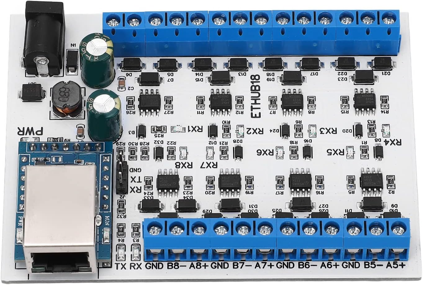
Figure 1: Top-down view of the EVTSCAN RJ45 to 8 RS485 Hub Converter, showing the RJ45 port, power input, and eight RS485 terminal blocks.
2. Specifications
| Feature | Specification |
|---|---|
| Item Type | RJ45 to 8 RS485 Hub Converter |
| Material | PCB |
| Operating Voltage | DC 7-30V (Nominal 12V, 24V) |
| Operating Current | 18-25mA |
| Installation | DIN35 and C45 rail compatible |
| Operating Modes | UDP, TCP, TCP to RTU, MQTT, HTTP |
| Default Baud Rate | 115200BPS (Configurable) |
| Parity Bits | No parity, Even parity, Odd parity |
| Dimensions | Approximately 3.94 x 3.15 x 1.18 inches |
| Weight | Approximately 2.26 ounces |
3. Setup and Installation
Follow these steps for proper installation and connection of your RJ45 to 8 RS485 Hub Converter.
3.1 Physical Installation
- Mounting: The module is designed for installation on DIN35 and C45 rails. Securely attach the converter to the desired rail in your control cabinet or enclosure.
- Environmental Considerations: Ensure the installation location is free from excessive moisture, dust, and extreme temperatures to maintain optimal performance and longevity.

Figure 2: The converter module shown in an industrial environment, illustrating its intended application in monitoring and control systems.
3.2 Power Connection
Connect a DC power supply within the range of 7-30V to the power input terminal (labeled 'VIN' or 'PWR'). Observe polarity: positive to VIN, negative to GND. The module typically operates at 12V or 24V DC.
3.3 RJ45 (Ethernet) Connection
Connect a standard Ethernet cable from your network device (e.g., router, switch, PC) to the RJ45 port on the converter. This port facilitates network communication for configuration and data transfer.

Figure 3: Detailed view of the RJ45 Ethernet port, indicating its location for network connectivity.
3.4 RS485 Connections
The converter features eight independent RS485 channels. Each channel has dedicated screw terminals for A+, B-, and GND. Connect your RS485 devices to these terminals, ensuring correct polarity for each connection.

Figure 4: Close-up of the blue screw terminal blocks for RS485 connections, showing the A+, B-, and GND labels for each channel.
4. Operating Modes and Configuration
The converter supports various operating modes and allows for flexible configuration of communication parameters.
4.1 Supported Operating Modes
The module can operate in the following modes:
- UDP: User Datagram Protocol for connectionless communication.
- TCP: Transmission Control Protocol for reliable, connection-oriented communication.
- TCP to RTU: Converts TCP/IP data to Modbus RTU protocol for RS485 devices.
- MQTT: Message Queuing Telemetry Transport for lightweight messaging.
- HTTP: Hypertext Transfer Protocol for web-based communication.
4.2 Baud Rate Adjustment
The default baud rate is 115200BPS. To adjust the baud rate, access the module's web configuration interface. The available baud rates are 1200, 2400, 4800, 9600, 19200, 38400, 57600, 115200, and 230400BPS. Select the rate that matches your RS485 devices.
4.3 Parity Bit Settings
The parity bits can be configured as no parity, even parity, or odd parity. This setting is crucial for ensuring correct data transmission with your RS485 devices and can be adjusted via the web interface.

Figure 5: An overview highlighting key features such as TVS surge protection, adjustable baud rate, and configurable parity bits.
5. Maintenance
To ensure the long-term reliability and performance of your EVTSCAN RJ45 to 8 RS485 Hub Converter, follow these maintenance guidelines:
- Regular Inspection: Periodically inspect the module for any visible damage, loose connections, or signs of overheating.
- Cleaning: If necessary, gently clean the exterior of the module with a soft, dry cloth. Avoid using liquid cleaners or solvents.
- Environmental Control: Maintain a stable operating environment within the recommended temperature and humidity ranges.
- Firmware Updates: Check the manufacturer's website for any available firmware updates that may improve performance or add new features.
6. Troubleshooting
If you encounter issues with your converter, consider the following troubleshooting steps:
- No Power: Verify that the DC power supply is connected correctly and providing the specified voltage (7-30V). Check the power indicator LED on the module.
- No Network Connectivity: Ensure the Ethernet cable is securely connected to both the converter and the network device. Check network settings and IP configuration.
- RS485 Communication Failure:
- Verify correct A+ and B- polarity for all RS485 connections.
- Confirm that the baud rate and parity bit settings on the converter match those of the connected RS485 devices.
- Check for proper termination resistors on the RS485 bus if applicable.
- Intermittent Communication: This could be due to electrical noise. Ensure proper grounding and consider using shielded cables for RS485 connections. The built-in TVS protection helps mitigate some transient issues.
- Module Unresponsive: If the module becomes unresponsive, try power cycling it (disconnect and reconnect power). If the issue persists, consult the manufacturer's support resources.
7. Warranty and Support
For warranty information, technical support, or further assistance, please refer to the official EVTSCAN website or contact your product vendor. Keep your purchase receipt or proof of purchase for warranty claims.
You can visit the EVTSCAN store for more information: EVTSCAN Store