
1. Introduction
This manual provides essential information for the proper installation, operation, and maintenance of the GIGABYTE GA-965P-DS3 motherboard. This component is designed to serve as a replacement part for compatible systems. Please read this manual thoroughly before proceeding with any installation or operation to ensure optimal performance and longevity of the product.
2. Safety Information
- Professional Installation Recommended: Due to the technical nature of motherboard installation, it is highly recommended that this product be installed by a qualified professional. Incorrect installation can lead to damage to the motherboard or other system components.
- Electrostatic Discharge (ESD) Precautions: Always handle the motherboard in an ESD-safe environment. Use an anti-static wrist strap and mat to prevent damage from static electricity, which can severely harm electronic components.
- Power Disconnection: Ensure the computer system is completely powered off and disconnected from the main power supply before installing or removing any components.
- Component Compatibility: Verify that all other components (CPU, RAM, GPU, power supply) are compatible with the GIGABYTE GA-965P-DS3 motherboard before installation.
- Handling Used Components: This product is a used component. While tested for full functionality, handle with care. Avoid touching pins or sensitive areas directly.
3. Product Overview
The GIGABYTE GA-965P-DS3 is a robust motherboard designed for Intel LGA 775 processors, supporting DDR2 memory. It features the Intel P965 Express Northbridge and ICH8 Southbridge chipsets, providing a stable foundation for personal computer systems. This section provides a visual reference and description of the motherboard's key components.
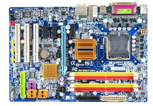
Figure 3.1: GIGABYTE GA-965P-DS3 Motherboard Layout
This image displays the full layout of the GIGABYTE GA-965P-DS3 motherboard. Key components visible include the LGA 775 CPU socket at the top right, surrounded by power delivery components. To the left of the CPU socket are four DDR2 DIMM slots (two yellow, two red) for memory modules. Below the CPU socket, the Northbridge heatsink (gold/copper colored) is visible, with the Southbridge heatsink (smaller, gold/copper colored) located further down. Various expansion slots, including PCIe x16 (blue), PCIe x1 (white), and PCI (white), are arranged vertically on the left side. The bottom edge features SATA ports (red), front panel headers, and USB headers. The rear I/O panel at the top left includes PS/2 ports, USB ports, Ethernet, and audio jacks.
4. Setup and Installation
Installing a motherboard requires careful attention to detail and adherence to safety protocols. It is strongly advised that individuals without prior experience seek professional assistance for installation.
4.1 Pre-Installation Checklist
- Ensure your power supply is compatible and provides sufficient wattage.
- Confirm your CPU (LGA 775 socket) and RAM (DDR2) are compatible with this motherboard.
- Gather necessary tools: Phillips head screwdriver, anti-static wrist strap, thermal paste.
- Prepare a clean, well-lit, and static-free workspace.
4.2 Installation Steps
- Prepare the Case: Remove the old motherboard if applicable. Install the I/O shield that came with your case or the replacement motherboard.
- Install the CPU: Carefully open the CPU socket lever. Align the CPU with the socket (match the golden triangle/notch) and gently place it in. Close the lever to secure the CPU. Apply a small amount of thermal paste to the CPU's heat spreader.
- Install the CPU Cooler: Mount the CPU cooler according to its manufacturer's instructions, ensuring proper contact with the CPU and secure attachment to the motherboard. Connect the CPU fan cable to the designated header.
- Install RAM: Open the clips on the DDR2 DIMM slots. Align the RAM modules with the slots (notch alignment is crucial) and press down firmly on both ends until the clips snap into place. Refer to your system's manual for optimal dual-channel configuration.
- Mount the Motherboard: Carefully place the motherboard into the computer case, aligning the screw holes with the standoffs. Secure the motherboard with screws, but do not overtighten.
- Connect Power Cables: Connect the 24-pin ATX main power connector and the 4-pin ATX 12V CPU power connector from your power supply to the motherboard.
- Connect Storage Devices: Connect SATA data cables from your hard drives/SSDs to the SATA ports on the motherboard. Connect SATA power cables from the power supply to the drives.
- Connect Front Panel Headers: Connect the power switch, reset switch, HDD LED, and power LED cables from the case to the corresponding headers on the motherboard. Pay close attention to polarity.
- Install Expansion Cards: Insert graphics cards into the PCIe x16 slot and other expansion cards (e.g., sound cards, network cards) into the appropriate PCIe x1 or PCI slots. Secure them with screws.
- Connect Case Fans and USB Headers: Connect any case fans to available fan headers and front panel USB ports to the motherboard's USB headers.
5. Operating Instructions
Once the motherboard and all components are correctly installed, you can proceed with initial system setup and operation.
- Initial Power On: Connect your monitor, keyboard, and mouse. Connect the power cord to the power supply and turn on the system.
- BIOS/UEFI Setup: During startup, press the designated key (usually DEL or F2) to enter the BIOS/UEFI setup utility. Configure basic settings such as date/time, boot order, and enable/disable integrated peripherals as needed. Save changes and exit.
- Operating System Installation: Insert your operating system installation media (USB drive or DVD) and follow the on-screen prompts to install your preferred operating system (e.g., Windows).
- Driver Installation: After OS installation, install all necessary drivers for the motherboard's chipsets, audio, network, and any discrete graphics cards. These are typically found on the manufacturer's website or an included driver disc.
- System Updates: Ensure your operating system and drivers are kept up-to-date for optimal performance and security.
6. Maintenance
Regular maintenance helps ensure the longevity and stable operation of your motherboard and overall system.
- Dust Removal: Periodically clean the interior of your computer case, especially the motherboard and heatsinks, using compressed air. Accumulation of dust can lead to overheating and poor contact in connectors, potentially causing system instability or failure.
- Check Connections: Ensure all power cables, data cables, and expansion cards are securely seated. Loose connections can cause intermittent issues.
- BIOS/Firmware Updates: Check the GIGABYTE support website for any available BIOS/firmware updates. Apply updates carefully, following manufacturer instructions, as incorrect updates can render the motherboard inoperable.
- Environmental Control: Operate the computer in a well-ventilated area, away from direct sunlight, excessive heat, or humidity.
7. Troubleshooting
This section provides basic troubleshooting steps for common issues you might encounter.
- System Does Not Power On:
- Check power supply connections to the motherboard (24-pin ATX and 4-pin CPU).
- Ensure the power supply switch is in the 'ON' position.
- Verify the front panel power switch cable is correctly connected to the motherboard header.
- No Display Output:
- Ensure the monitor is connected to the correct graphics output (either integrated or discrete GPU).
- Reseat the graphics card and RAM modules.
- Try booting with only one RAM stick.
- System Instability or Random Restarts:
- Check for overheating. Ensure CPU cooler is properly installed and fans are spinning.
- Verify RAM is correctly seated and functional. Run a memory diagnostic tool.
- Inspect the motherboard for any visible damage, burnt components, or signs of poor contact due to rust, oxidation, or dust.
- Ensure all drivers are up-to-date.
- Peripheral Not Detected:
- Check the connection of the peripheral to the motherboard.
- Ensure necessary drivers are installed.
- Verify the peripheral is enabled in the BIOS/UEFI settings.
If issues persist after basic troubleshooting, consult a professional technician.
8. Specifications
| Feature | Detail |
|---|---|
| Brand | GIGABYTE (Generic listed as seller brand) |
| Model | GA-965P-DS3 |
| CPU Socket | LGA 775 |
| Compatible Processors | Intel Core 2 Extreme Quad-Core / Core 2 Duo / Intel Pentium Extreme / Intel Pentium D processor (Supports 1066/800/533 MHz FSB) |
| Chipset Type | Northbridge: Intel P965 Express Chipset, Southbridge: Intel ICH8 |
| RAM Memory Technology | DDR2 |
| Memory Clock Speed | 800 MHz (Max) |
| Memory Slots Available | 4 |
| Compatible Devices | Personal Computer |
| Platform | Windows |
| Product Dimensions | 12 x 9 x 2 inches (12"L x 9"W x 2"H) |
| Manufacturer | GIGA |
9. Warranty and Support
This GIGABYTE GA-965P-DS3 motherboard is a used product. The seller guarantees that all products are tested before shipment to ensure normal operation of all functions. Specific warranty terms beyond this initial functionality guarantee should be clarified directly with the seller at the time of purchase.
For technical support or inquiries regarding this specific used item, please contact the seller directly. For general product information or driver downloads, refer to the official GIGABYTE website for the GA-965P-DS3 model.


