
Introduction
The BANRIA 4-Digit Electronic Clock Building Kit is designed to provide a practical and engaging introduction to electronics, soldering, and microcontroller-based circuits. This kit is ideal for beginners, students, and hobbyists interested in understanding basic technical contexts through hands-on assembly. The finished clock features a 4-digit LED display and a transparent casing, allowing the internal components to be visible.
Safety Information
- Warning: Not suitable for children under 14 years of age. Adult supervision is recommended during assembly, especially for soldering.
- Always wear appropriate safety glasses when soldering.
- Ensure adequate ventilation in your workspace to avoid inhaling solder fumes.
- Handle electronic components with care to prevent damage from static electricity.
- Keep small components out of reach of young children to prevent choking hazards.
Package Contents
Verify that all components listed below are present in your kit. If any parts are missing or damaged, please contact customer support.

Image: Overview of all components included in the kit, such as the PCB, LED display, buttons, resistors, capacitors, crystal oscillator, battery holder, CR2032 battery, transparent case parts, silicone strap, and a small screwdriver.
- Main Printed Circuit Board (PCB)
- 4-Digit 7-Segment Red LED Display
- Microcontroller (pre-programmed)
- Push Buttons (2x)
- Resistors, Capacitors, Crystal Oscillator
- CR2032 Battery Holder
- CR2032 Lithium Battery (3V)
- Transparent Acrylic Case Parts
- Silicone Wrist Strap (adjustable)
- Small Screwdriver
- Assembly Screws and Nuts
- Illustrated Step-by-Step Guide (physical or digital)
Specifications
| Component Type | Through-Hole Technology (THT) |
| Display Type | 0.28-inch 4-Digit 7-Segment Red LED |
| Case Material | Transparent Acrylic |
| Strap Material | Silicone (skin-friendly and flexible) |
| Case Dimensions (L x W x H) | 50 mm x 45 mm x 15 mm (approx. 2 x 1.8 x 0.6 inches) |
| Strap Length (unfolded) | 90 mm + 120 mm (adjustable, total 260 mm) |
| Strap Width | 16 mm |
| Power Source | CR2032 3V Lithium Battery |
| Recommended Age | 14 years and older |
| Model Number | EM21810-2 |

Image: Wrist size guide for the silicone strap, indicating suitability for wrist circumferences between 10.5 cm and 18.7 cm.
Setup and Assembly
This kit requires soldering. Follow the included step-by-step guide carefully. The components are all through-hole (THT), making this kit suitable for beginners to practice soldering techniques.
- Prepare Your Workspace: Ensure a clean, well-lit, and well-ventilated area. Gather your soldering iron, solder, desoldering wick/pump, and safety glasses.
- Identify Components: Refer to the component list and the circuit diagram in the included guide to identify each part.
- Solder Components: Solder the components onto the PCB, starting with the smallest parts (resistors, capacitors) and progressing to larger ones (microcontroller, LED display, buttons, battery holder). Pay close attention to component polarity where indicated.
- Test Functionality: Before final assembly of the case, insert the CR2032 battery and briefly test the circuit to ensure the display lights up and buttons respond.
- Assemble the Case: Carefully mount the assembled PCB into the transparent acrylic case parts using the provided screws and nuts. Ensure the buttons align with the case openings.
- Attach the Strap: Connect the silicone wrist strap to the assembled clock case.

Image: An individual demonstrating soldering of through-hole components, highlighting the kit's suitability for soldering practice.

Image: Circuit diagram illustrating the electrical connections of the clock components.
Operating Instructions
The clock is operated using two buttons, typically labeled S1 and S2, or similar. These buttons allow for time adjustment and display activation.
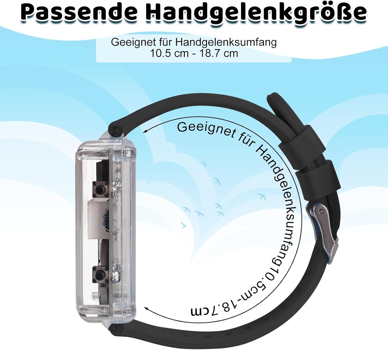
Image: Function settings diagram, showing the two buttons for adjusting minutes and hours.
- Activate Display: The display automatically turns off after approximately 10 seconds to conserve power. Press any button to reactivate the display.
- Set Minutes: Press and hold the designated 'Minute Set' button (e.g., S1). The minute digits will start to flash. Continue holding to advance minutes rapidly, or press repeatedly for single-minute adjustments. Release the button to confirm.
- Set Hours: Press and hold the designated 'Hour Set' button (e.g., S2). The hour digits will start to flash. Continue holding to advance hours rapidly, or press repeatedly for single-hour adjustments. Release the button to confirm.
- Power Saving Mode: The clock automatically enters a power-saving mode by turning off the LED display after about 10 seconds of inactivity. This extends battery life.
Maintenance
- Battery Replacement: When the display dims or the clock stops functioning, replace the CR2032 battery. Carefully open the transparent case using the provided screwdriver, remove the old battery, and insert a new one with the correct polarity.
- Cleaning: Wipe the transparent case and silicone strap with a soft, dry cloth. Avoid using harsh chemicals or abrasive materials.
- Strap Care: The silicone strap is designed for comfort and easy disassembly. It can be removed for cleaning or replacement if needed.
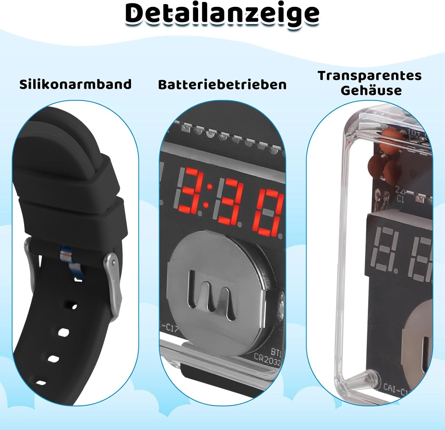
Image: The comfortable and easily detachable silicone strap.

Image: Detail view showing the silicone strap, battery compartment, and transparent case.
Troubleshooting
| Problem | Possible Cause | Solution |
|---|---|---|
| Clock does not power on / Display is blank. | 1. Battery is dead or incorrectly inserted. 2. Poor solder joint. 3. Component inserted with incorrect polarity. |
1. Replace battery or check polarity (+/-). 2. Inspect all solder joints for cold joints or bridges. Re-solder as needed. 3. Verify polarity of diodes, LEDs, and ICs. |
| Display is dim or flickers. | Low battery power. | Replace the CR2032 battery. |
| Buttons do not respond. | 1. Button not soldered correctly. 2. Button is faulty. 3. Microcontroller issue. |
1. Check solder joints for the buttons. Re-solder. 2. If possible, test button continuity with a multimeter. Replace if faulty. 3. Ensure microcontroller is correctly soldered and oriented. |
| Time is inaccurate. | Faulty crystal oscillator or capacitor. | Check solder joints for the crystal oscillator (Y1) and its associated capacitors (C1, C2). Ensure correct component values. |
For further assistance, refer to the detailed troubleshooting section in your included instruction guide or contact BANRIA customer support.
Warranty and Support
This BANRIA product is designed for educational purposes and DIY assembly. Due to the nature of a soldering kit, warranty coverage typically applies to manufacturing defects of individual components prior to assembly. Once components are soldered, issues often relate to assembly errors.
- Component Defects: If you discover a defective component upon opening the package and before assembly, please contact your retailer or BANRIA customer support for a replacement.
- Technical Support: For assembly questions, troubleshooting assistance, or general inquiries, please refer to the comprehensive guide included with your kit. If further support is needed, contact BANRIA customer service through the contact information provided on the product packaging or the official BANRIA website.
- Online Resources: Check the BANRIA website for additional resources, FAQs, or updated guides.
