
Sonel PVM-1020
Sonel PVM-1020 Photovoltaic Meter and IRM-1 Solar Radiation Temperature Meter User Manual
Model: PVM-1020
1. Introduction
The Sonel PVM-1020 Photovoltaic Meter, paired with the IRM-1 Solar Radiation Temperature Meter, forms a comprehensive solution for testing and diagnosing photovoltaic systems. The PVM-1020 is designed for a wide range of electrical measurements on PV installations, while the IRM-1 provides crucial environmental data for accurate performance analysis under Standard Test Conditions (STC).
This manual provides detailed instructions for the safe and effective use of both devices, covering setup, operation, maintenance, and troubleshooting.
2. Key Features
PVM-1020 Photovoltaic Meter
- Open circuit voltage of PV panel or chain (up to 1000V DC).
- RMS voltage of AC network (up to 600V with frequency measurement).
- Short circuit current of PV panel or chain (up to 20A DC).
- Insulation resistance of PV panels (250V, 500V, 1000V; RISO+ and RISO-).
- Insulation resistance of AC circuits (250V, 500V, 1000V).
- Resistance of protective conductors and equipotential bonding (±200mA current).
- Measurement of PV panels operating current and AC current (with external clamp).
- AC/DC power measurement.
- Diode test (200mA current, automatic polarity detection, blocking diodes with 1000V DC).
- Category 1 measurements according to IEC 62446-1.
- AUTO mode for performing a sequence of measurements.
- Converts measured parameters into STC conditions with IRM-1 (IEC 60891).
- LoRa and Bluetooth communication interfaces.
- Large measurement memory (999 cache cells, 5000 recorder records).
- Backlit graphic display and buttons for ease of use in shaded areas.
IRM-1 Solar Radiation Temperature Meter
- Measurement of solar radiation intensity (Irradiance) in W/m² or BTU/ft².
- PV panel temperature in °C or °F.
- Ambient temperature in °C or °F.
- Inclination angle of panels.
- Orientation of panels with built-in compass.
- LoRa interface for communication with master meter (extended range).
- Automatic data synchronization with master meter (reSYNC function).
- Built-in recorder for PV plant design process and shading diagnosis (5000 records).
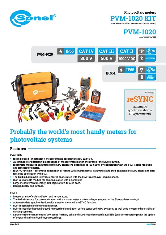
Figure 2.1: Overview of PVM-1020 and IRM-1 features and capabilities.
3. What's in the Box
The Sonel PVM-1020 Photovoltaic Meter kit includes the following components:
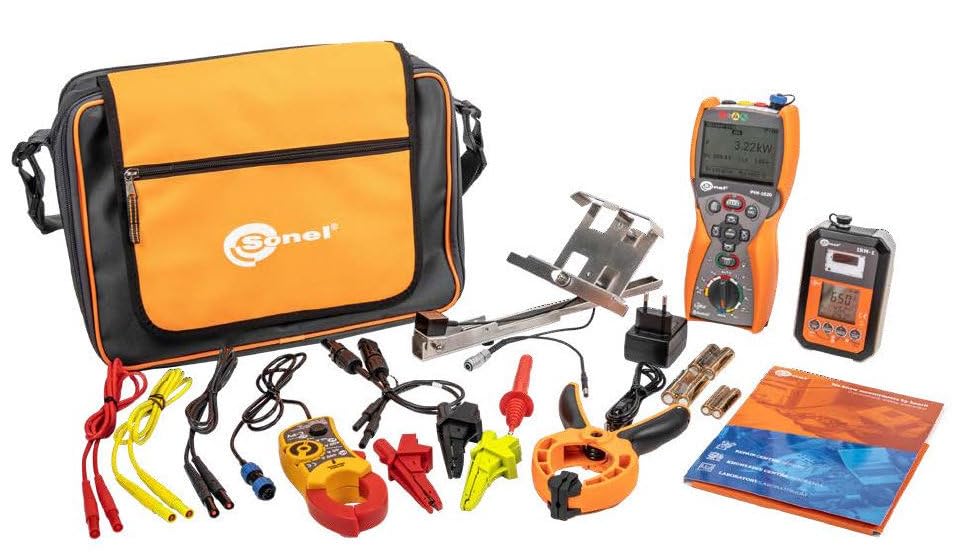
Figure 3.1: All components included in the Sonel PVM-1020 and IRM-1 kit.
| Item | Description | Quantity |
|---|---|---|
| PVM-1020 | Photovoltaic Meter | 1 |
| IRM-1 | Solar Radiation and Temperature Meter | 1 |
| Mounting Kit | Solar Radiation Meter mounting kit for PV panels + probe for measuring temperature | 1 |
| Test Leads | 1.2m 1kV (banana plugs) black / blue / yellow | 3 |
| Crocodile Clips | 1kV 20A black / red / yellow | 3 |
| Pin Probe | 1kV (banana socket) red | 1 |
| MC4 Adapter | MC4-banana sockets adapter (set of 2 pcs.) | 1 |
| C-PV Clamp | C-PV current clamp | 1 |
| Power Supply | 5V power supply with USB 2.0 output and detachable micro-USB cable | 1 |
| Hanging Straps | M1 hanging straps | 1 |
| Carrying Cases | M6 carrying case and L4 carrying case | 2 |
| Batteries | AA 1.5V battery (4 pcs), AAA 1.5V battery (2 pcs) | 6 |
| Certificates | Factory calibration certificate - PVM-1020 and IRM-1 | 2 |
4. Setup and Initial Operation
4.1. Battery Installation
Ensure that the AA and AAA batteries are correctly installed in both the PVM-1020 and IRM-1 devices according to the polarity markings in the battery compartments. Use fresh batteries for optimal performance.
4.2. Powering On
To power on the PVM-1020, rotate the main switch to any measurement function. The IRM-1 typically powers on automatically when connected or activated for measurement.
4.3. Connecting Accessories
Connect the appropriate test leads, clamps, or probes to the PVM-1020's input terminals based on the measurement type. For PV panel temperature and radiation measurements, attach the IRM-1 to the PV panel using the provided mounting kit.
5. Operating Instructions
5.1. PVM-1020 Measurement Functions
The PVM-1020 offers a wide array of measurement functions, selected via a rotary switch and fine-tuned with additional buttons. The backlit display facilitates operation in low-light conditions.
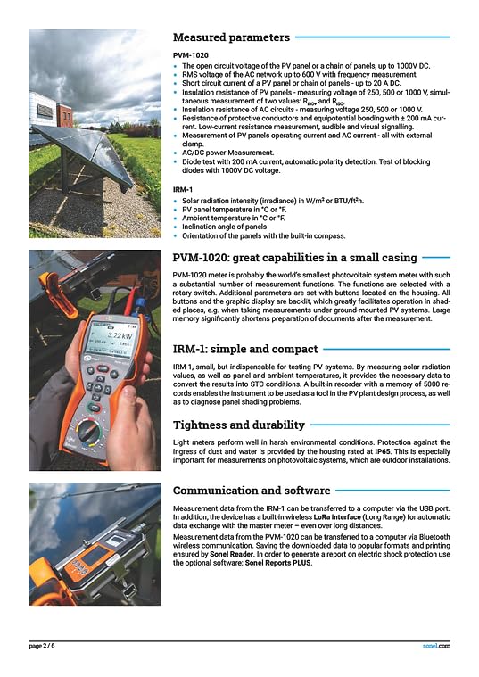
Figure 5.1: Detailed list of measured parameters for PVM-1020 and IRM-1.
- Open Circuit Voltage (Uoc): Connect test leads to the PV panel/chain terminals. Select the Uoc function.
- Short Circuit Current (Isc): Use the C-PV clamp to measure current. Select the Isc function.
- Insulation Resistance (Riso): Select the desired test voltage (250V, 500V, or 1000V). Connect leads to perform RISO+ and RISO- measurements simultaneously.
- Resistance of Protective Conductors (Rcont): Use the appropriate leads for ±200mA current measurement.
- Diode Test: Connect leads to the diode. The meter automatically detects polarity.
- AC/DC Power Measurement: Utilize external clamps for current measurement in conjunction with voltage readings.
- AUTO Mode: Press the START button to initiate a sequence of predefined measurements, streamlining the testing process.
5.2. IRM-1 Solar Radiation and Temperature Measurement
The IRM-1 is crucial for converting measurement results to STC. Ensure it is positioned correctly to capture accurate solar radiation and temperature data.
- Mounting: Use the provided mounting kit to securely attach the IRM-1 to the PV panel surface for accurate panel temperature readings.
- Orientation: Utilize the built-in compass and inclination sensor to ensure the IRM-1 is oriented correctly relative to the PV panels for precise solar radiation measurements.
- Data Recording: The IRM-1's built-in recorder can log up to 5000 records, useful for long-term monitoring, PV plant design, and shading analysis.
5.3. reSYNC Function
The reSYNC function ensures data integrity and accuracy by automatically synchronizing environmental parameters from the IRM-1 with the PVM-1020's measurements, even if the connection is temporarily lost.
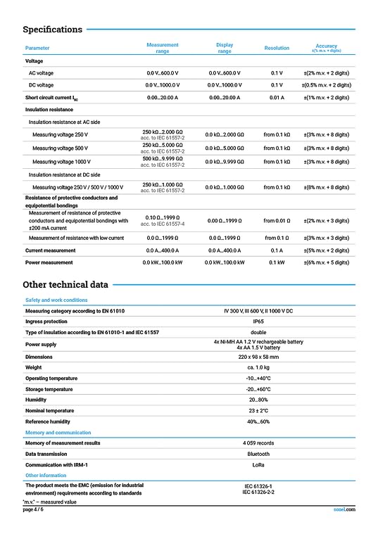
Figure 5.2: Diagram illustrating the reSYNC function's operation.
If the master meter (PVM-1020) moves away from the IRM-1 and communication is interrupted, measurements on the PVM-1020 can continue. Once the connection is restored, the PVM-1020 automatically retrieves the environmental parameters (E, T) from the IRM-1's temporary memory and converts the previously recorded results to STC conditions.
6. Maintenance
6.1. Cleaning
Clean the device casing with a soft, damp cloth. Do not use abrasive cleaners or solvents. Ensure all ports and connections are free from dust and debris.
6.2. Battery Replacement
Replace batteries when the low battery indicator appears on the display. Always use the specified battery type (AA and AAA 1.5V). Remove batteries if the device will not be used for an extended period to prevent leakage.
6.3. Calibration
Regular calibration is essential to maintain the accuracy of the PVM-1020 and IRM-1. Refer to the included factory calibration certificates for details. It is recommended to have the devices professionally calibrated annually or as required by local regulations.
6.4. Storage
Store the devices in their carrying cases in a dry, cool environment, away from direct sunlight and extreme temperatures. The operating temperature range is -10°C to +50°C, and storage temperature is -20°C to +60°C.
7. Troubleshooting
7.1. Device Not Powering On
- Check battery levels and ensure they are correctly installed.
- Replace batteries with new ones.
- Ensure the rotary switch is set to a valid measurement function.
7.2. Communication Issues (PVM-1020 and IRM-1)
- Ensure both devices are within LoRa communication range.
- Check for any physical obstructions between the devices.
- Verify that the reSYNC function is enabled on both devices if automatic synchronization is desired.
- If communication is lost, the reSYNC function will automatically update data once connection is re-established.
7.3. Inaccurate Readings
- Ensure test leads and probes are securely connected and not damaged.
- Verify that the correct measurement function is selected.
- For IRM-1, ensure proper orientation and mounting on the PV panel for accurate environmental data.
- Consider professional calibration if inaccuracies persist.
8. Specifications
8.1. PVM-1020 Electrical Specifications
| Parameter | Measurement Range | Display Range | Resolution | Accuracy |
|---|---|---|---|---|
| AC voltage | 0.0...600.0 V | 0.0...600.0 V | 0.1 V | ±(2% m.v. + 2 digits) |
| DC voltage | 0.0...1000.0 V | 0.0...1000.0 V | 0.1 V | ±(0.5% m.v. + 2 digits) |
| Short circuit current Isc | 0.00...20.00 A | 0.00...20.00 A | 0.01 A | ±(1% m.v. + 8 digits) |
| Insulation resistance | ||||
| Insulation resistance at AC side | ||||
| Measuring voltage 250 V | 250 kΩ...2.000 GΩ | 0.0 kΩ...2.000 GΩ | 0.1 kΩ | ±(3% m.v. + 8 digits) |
| Measuring voltage 500 V | 250 kΩ...5.000 GΩ | 0.0 kΩ...5.000 GΩ | 0.1 kΩ | ±(3% m.v. + 8 digits) |
| Measuring voltage 1000 V | 500 kΩ...9.999 GΩ | 0.0 kΩ...9.999 GΩ | 0.1 kΩ | ±(3% m.v. + 8 digits) |
| Insulation resistance at DC side | ||||
| Measuring voltage 250 V / 500 V / 1000 V | 250 kΩ...1.000 GΩ | 0.0 kΩ...1.000 GΩ | 0.1 kΩ | ±(3% m.v. + 8 digits) |
| Resistance of protective conductors and equipotential bondings | ||||
| Measurement of resistance of protective conductors and equipotential bondings with ±200 mA current | 0.10 Ω...1999 Ω | 0.00 Ω...1999 Ω | 0.01 Ω | ±(2% m.v. + 3 digits) |
| Measurement of resistance with low current | 0.0 Ω...199.9 Ω | 0.0 Ω...199.9 Ω | 0.1 Ω | ±(3% m.v. + 3 digits) |
| Current measurement | 0.0 A...400.0 A | 0.0 A...400.0 A | 0.1 A | ±(5% m.v. + 2 digits) |
| Power measurement | 0.0 kW...100.0 kW | 0.0 kW...100.0 kW | 0.1 kW | ±(5% m.v. + 2 digits) |
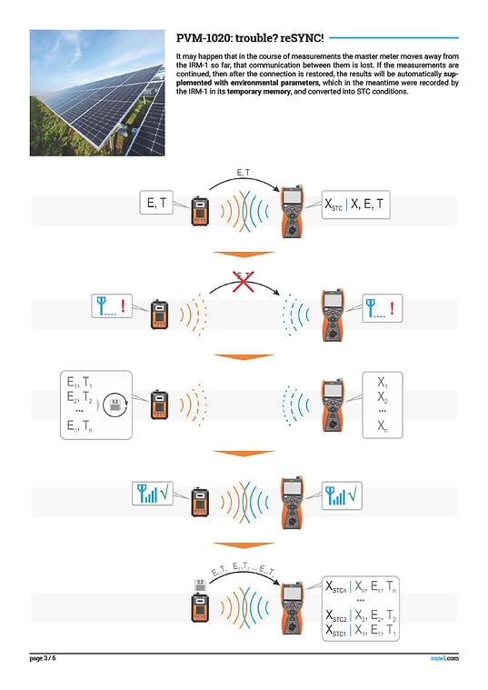
Figure 8.1: Comprehensive technical specifications for the PVM-1020 and IRM-1.
8.2. General Technical Data
- Measuring Category: IV 300V, III 600V DC according to EN 61010.
- Ingress Protection: IP65 (dust tight and protected against water jets).
- Type of Insulation: Double according to EN 61010-1 and IEC 61557.
- Power Supply: PVM-1020: 4x Ni-MH AA 1.2V rechargeable battery; IRM-1: 4x AA 1.5V battery.
- Dimensions: 220 x 98 x 58 mm.
- Weight: Approx. 1.0 kg.
- Operating Temperature: -10°C to +50°C.
- Storage Temperature: -20°C to +60°C.
- Humidity: 20...80%.
- Nominal Temperature: 23 ± 2°C.
- Reference Humidity: 40%...60%.
8.3. Memory and Communication
- Memory of Measurement Results: 4059 records.
- Data Transmission: Bluetooth.
- Communication with IRM-1: LoRa.
9. Warranty and Support
9.1. Warranty Information
The Sonel PVM-1020 and IRM-1 come with a 1-year manufacturer's warranty. This warranty covers defects in materials and workmanship under normal use. Please retain your proof of purchase for warranty claims.
9.2. Technical Support
For technical assistance, troubleshooting beyond this manual, or warranty service, please contact Sonel customer support or your authorized distributor. Have your product model and serial number ready when contacting support.
For the latest software updates and additional resources, please visit the official Sonel website.
Related documentsPVM-1020


Ask a question about this manual
Ask about setup, troubleshooting, compatibility, parts, safety, or missing instructions. Manuals+ will review the question and use this page’s manual context to help answer it.