
GCSOAR 80A PWM Solar Charge Controller User Manual
Model: GCVT8048
Brand: GCSOAR
1. Introduction
The GCSOAR 80A PWM Solar Charge Controller is designed to manage the power flow from your solar panels to your battery bank and DC loads. It automatically detects 12V, 24V, 36V, or 48V system voltages and supports a wide range of battery types, including Sealed, Flooded, GEL (AGM), LiFePO4, and ternary lithium batteries. This controller features a backlit LCD screen for real-time monitoring and offers multiple protection functions to ensure safe and efficient operation of your solar power system.
Key Features:
- Automatic System Voltage Detection: Compatible with 12V, 24V, 36V, and 48V systems.
- High Power Input: Supports up to 1000W for 12V, 2000W for 24V, 3000W for 36V, and 4000W for 48V battery systems.
- Versatile Battery Compatibility: Works with Sealed, Flooded, GEL (AGM), LiFePO4, and ternary lithium batteries, with user-defined options.
- PWM 3-Stage Charging: Utilizes Bulk, Boost, and Float charging modes for efficient and extended battery life.
- Integrated USB Output: Features Quattro USB outputs (5V/2A max) for charging mobile devices.
- Backlit LCD Display: Provides real-time monitoring of charging current, generated energy, temperature, battery voltage, and error codes.
- Comprehensive Protections: Includes solar panel reverse-polarity, battery reverse-polarity, battery reverse-discharge, over-heating, battery over-current, load over-load, and load short-circuit protection.
2. Setup and Installation
Proper installation is crucial for the safe and efficient operation of your solar charge controller. Please follow these steps carefully.
2.1 Wiring Connection Steps
Important: Connect and disconnect components in the specified order to prevent damage to the controller or other system components.

Image: Connection diagram illustrating the correct sequence for connecting and disconnecting system components.
- Connect the Battery (1): Connect the battery to the charge controller first. Ensure correct polarity (positive to positive, negative to negative). The controller will automatically detect the battery voltage.
- Connect the DC Load (2): Connect the DC load to the charge controller. Ensure correct polarity.
- Connect the Solar Panels (3): Connect the solar panels to the charge controller last. Ensure correct polarity.
To Disconnect: Follow the reverse order: Solar Panels (3) → DC Load (2) → Battery (1).

Image: Detailed connection diagram including solar panel, battery, inverter, and AC/DC loads, with battery display information.
2.2 Mounting and Wiring Guidelines
- Mount the controller in a well-ventilated area, away from direct sunlight and heat sources.
- Ensure sufficient space around the controller for heat dissipation.
- Use appropriate wire gauges. Recommended wire cable for the 80A model is #4AWG (25mm²).
- The controller uses common positive grounding.
- Mounting hole size: 190mm x 104mm with Φ5mm holes.
- Dimensions: 200mm x 131.6mm x 72mm.
3. Operating Instructions
The GCSOAR solar charge controller features an intuitive LCD display and control buttons for easy operation and monitoring.
3.1 LCD Display and Key Description
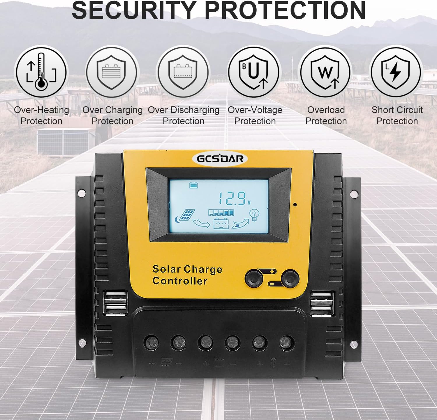
Image: Front and side view of the controller with labels for LCD screen, buttons, USB ports, and connection terminals.
- LCD Screen: Displays system status, parameters, and settings.
- Browse / Set Button: Used to navigate through display interfaces and adjust parameters.
- Set Button: Used to enter/exit setting mode and confirm selections.
- USB Ports: Four 5V/2A (max) USB outputs for charging external devices.
- Solar Panel Terminals: Connect positive and negative leads from solar panels.
- Battery Terminals: Connect positive and negative leads from the battery bank.
- Load Terminals: Connect positive and negative leads for DC loads.
3.2 Browsing the Interface
Press the 'Browse / Set' button to cycle through various display screens, showing real-time system information.

Image: Examples of LCD display interfaces, including battery voltage, temperature, charging/discharging data, and battery type selection.
The display will show information such as:
- Battery Voltage (Main Display)
- Ambient Temperature
- Charging Voltage
- Power Consumption
- Discharging Current
- Power Generation
- Charging Current
- Load Working Mode (Time1, Time2)
- Battery Types
3.3 Setting Parameters
To enter setting mode, press and hold the 'Set' button until the parameter starts flashing. Use the 'Browse / Set' button to adjust the value, then press 'Set' again to confirm and move to the next parameter or exit setting mode.
3.3.1 Battery Type Selection
The controller supports various battery types. Select the correct type for optimal charging and protection.

Image: Visual representation of compatible battery types: Lithium, Flooded, Sealed, Gel, and User-defined.
Available battery types include:
- Sealed (default)
- Gel (AGM)
- Flooded
- LiFePO4 (Lithium Iron Phosphate)
- Li(NiCoMn)O2 (Ternary Lithium)
- User-defined (for custom voltage settings)
For Lithium batteries, the voltage cannot be auto-identified; you must manually select the correct Li-type in the controller settings.
3.3.2 Load Control Settings
The controller allows for adjustment of load enable duration, combining solar light control and time control features.
4. Maintenance
Regular maintenance ensures the longevity and optimal performance of your solar charge controller and system.
- Inspect Connections: Periodically check all wiring connections for tightness and corrosion. Loose connections can cause overheating and power loss.
- Clean Terminals: Ensure battery and solar panel terminals are clean and free of dirt or oxidation.
- Ventilation: Verify that the controller's ventilation openings are not blocked to allow for proper heat dissipation.
- Environmental Check: Ensure the controller is not exposed to excessive moisture, dust, or extreme temperatures outside its operating range.
- Battery Health: Monitor battery voltage and health regularly, especially for lead-acid batteries, to ensure they are being charged correctly.
5. Troubleshooting
The GCSOAR solar charge controller is equipped with multiple protection features and an LCD display that can help identify potential issues.
5.1 Protection Features
The controller includes the following built-in protections:
- Solar panel reverse-polarity protection
- Battery reverse-polarity protection
- Battery reverse-discharge protection
- Over-heating protection
- Battery over-current protection
- Load over-load protection
- Load short-circuit protection
- Battery low-voltage protection
Image: Visual representation of the security protection features integrated into the GCSOAR solar charge controller.
5.2 Common Issues and Solutions
- No Display / No Power: Check battery connections and ensure the battery has sufficient charge.
- No Charging: Verify solar panel connections and ensure adequate sunlight. Check for any error codes on the LCD.
- Load Not Working: Check load connections, ensure the load is not overloaded or short-circuited. Verify load control settings.
- Error Codes: The LCD screen will display specific error codes. Refer to the controller's detailed manual (if available) or contact support with the code for further assistance.
- Incorrect Voltage Readings: Ensure the correct battery type is selected in the settings. Calibrate battery voltage if necessary (user-defined battery types).
6. Specifications
Detailed technical specifications for the GCSOAR 80A PWM Solar Charge Controller (Model GCVT8048).

Image: Table of applicable battery types and their voltage parameters for various system voltages.
| Parameter | Value |
|---|---|
| Model | GCVT8048 |
| Rated Charge Current | 80 Amp |
| Rated Discharge Current | 40 Amp |
| Nominal System Voltage | 12V/24V/36V/48V DC Auto |
| Max. PV Input Power | 1000W @ 12V BAT; 2000W @ 24V BAT; 3000W @ 36V BAT; 4000W @ 48V BAT |
| Max. PV Open Circuit Voltage | 50V @ 12V/24V BAT system (46V @ 25℃); 100V @ 36V/48V BAT system (92V @ 25℃) |
| Battery Voltage Range | 8V ~ 68V |
| Grounding | Common Positive Grounding |
| Temperature Compensation | -4mV/℃/2V (25℃) |
| Working Environment Temperature | -20℃ ~ +50℃ |
| Protection Category | IP30 |
| USB Output | 5V/2A * 2 (Quattro USB) |
| LCD Backlight Time | 30S (Default) |
| Controller Terminals | #4AWG (25mm²) |
| Recommended Wire Cable | #4AWG (25mm²) |
| Mounting Hole Size | 190mm * 104mm ~ Φ5mm |
| Dimension | 200mm * 131.6mm * 72mm |
| Weight | 0.79 KG |
7. Warranty and Support
For warranty information, please refer to the documentation provided with your purchase or contact the seller directly. GCSOAR stands behind its products, and any warranty claims or technical support inquiries should be directed to the point of purchase or the official GCSOAR customer service channels.
When contacting support, please have your product model (GCVT8048) and purchase details readily available.