1. Introduction
This manual provides essential information for the safe and efficient operation of your PowMr 10000W Hybrid Solar Inverter. It is designed for use in 48V DC to 110V/240V AC split-phase systems, featuring a 200A MPPT controller. Please read this manual thoroughly before installation and use, and retain it for future reference.

Figure 1: Front view of the PowMr 10000W Hybrid Solar Inverter.
2. Safety Instructions
WARNING: Electrical shock hazard. Installation and maintenance must be performed by qualified personnel only.
- Ensure all power sources (PV, battery, AC utility) are disconnected before performing any wiring or maintenance.
- Use appropriate personal protective equipment (PPE) including insulated gloves and eye protection.
- Verify correct polarity for all DC connections (PV and battery). Incorrect polarity can cause severe damage to the inverter and connected equipment.
- Ensure proper grounding of the inverter as per local electrical codes.
- Do not operate the inverter if it is damaged or appears to be malfunctioning.
- Keep children and unauthorized persons away from the inverter and its connections.
- Install the inverter in a well-ventilated area, away from flammable materials and direct sunlight.
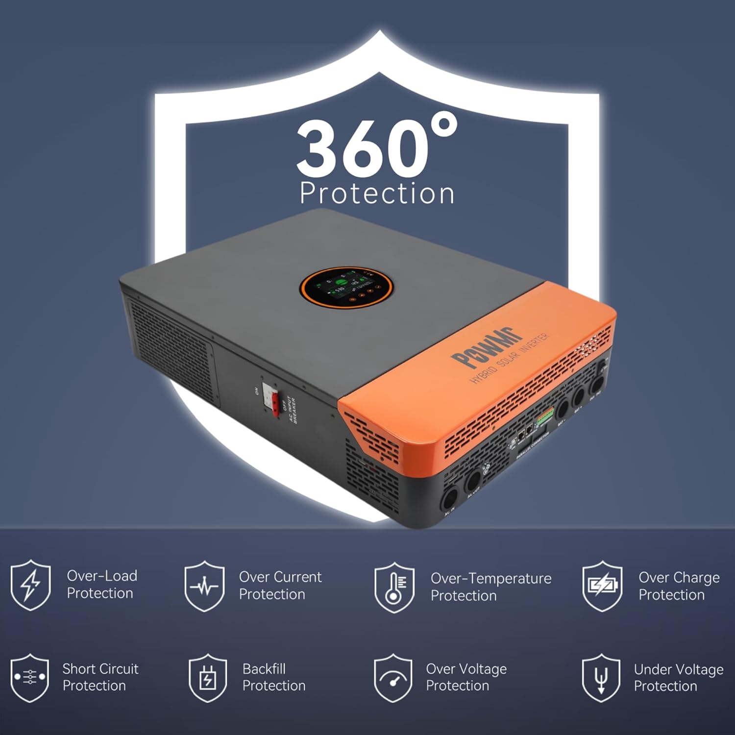
Figure 2: The inverter features comprehensive protection mechanisms including overload, over current, over temperature, over charge, short circuit, backfill, over voltage, and under voltage protection.
3. Product Overview
3.1 Key Features
- Supports both split-phase (120V/240V) and single-phase (120V) pure sine wave AC output.
- Integrated dual 100A MPPT solar charge controllers with 99.9% efficiency.
- Maximum PV input power of 11KW (5500W per MPPT input), with a maximum PV input voltage of 500V DC.
- Four selectable battery charging modes: Only Solar, Utility Priority, Solar Priority, and Utility & Solar Hybrid.
- Four AC output working modes: PV Priority, Utility Priority, Inverter Priority, and Solar & Utility Hybrid.
- Compatible with 48V lead-acid (Seal, AGM, Gel, Flooded) and lithium batteries. Supports batteryless operation.
- Comprehensive protection features: short circuit, over-current, over/under voltage, overload, and backfeed protection.
- Communication ports: CAN, USB, RS485, Dry contact.
3.2 Product Components

Figure 3: Inverter components and connection points.
| No. | Component | No. | Component |
|---|---|---|---|
| 1 | LCD screen | 9 | CAN/RS485-2 port |
| 2 | LED Indicators | 10 | RS485-1 port |
| 3 | Touchable key | 11 | USB-B port |
| 4 | ON/OFF Rocker Switch | 12 | Grounding Screw |
| 5 | PV INPUT (1/1) | 13 | AC OUT (L+L+N) |
| 6 | BAT INPUT (+) | 14 | AC IN (L+L+N) |
| 7 | BAT INPUT (-) | 15 | AC INPUT breaker |
| 8 | Dry contact | 16 | Parallel Communication Port |

Figure 4: Overview of the inverter's communication interfaces.
4. Specifications
| Specification | Value |
|---|---|
| Rated Output Power | 10000W (continuous), 20000W (surge) |
| Rated Output Voltage | 120/240Vac (split-phase/single-phase) |
| Maximum PV Input Power | 11KW (5500W per MPPT input) |
| Maximum PV Input Voltage | 500V DC |
| PV Starting Voltage | ≥150V |
| MPPT Controller Current | Dual 100A (22A per circuit) |
| Rated Battery Input | 48V |
| Compatible Battery Types | Lead-acid (Seal, AGM, Gel, Flooded), Lithium |
| Communication Ports | CAN/USB/RS485/Dry contact |
| Product Dimensions | 17.5 x 5.12 x 24.4 inches |
| Item Weight | 53.9 pounds |
| Model Name | POW-SunSmart 10K |
5. Setup and Installation
5.1 Mounting
- Mount the inverter vertically on a sturdy wall or surface.
- Ensure adequate clearance around the inverter for proper ventilation (at least 20 cm on all sides).
- Avoid mounting in direct sunlight, high humidity, or dusty environments.
5.2 Wiring Connections
All wiring must comply with local and national electrical codes. Use appropriately sized conductors for all connections.
5.2.1 Split-Phase Wiring Diagram (120V/240V AC Output)
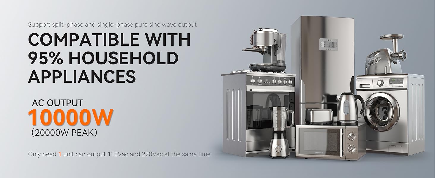
Figure 5: Split-phase wiring configuration for 120V/240V AC output.
- PV Input: Max PV array power 11,000W, Max VOC 500V, MPPT voltage range 125-425VDC. Use 10AWG PV wire.
- Battery: Rated voltage 48V. Use 1 AWG cable, 2P-250A circuit breaker.
- AC Input: Use 6AWG (L1/L2/N) cable, 3P-63A circuit breaker.
- Inverter Output: Rated power 10,000W, Surge power 20,000W. Default output voltage 120/240V. Use 6AWG (L1/L2/N) cable, 3P-63A circuit breaker.
5.2.2 Single-Phase Wiring Diagram (120V AC Output)
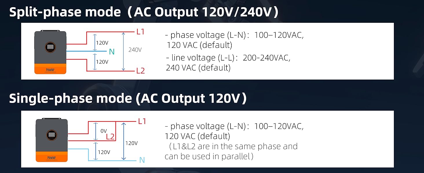
Figure 6: Single-phase wiring configuration for 120V AC output.
- PV Input: Max PV array power 11,000W, Max VOC 500V, MPPT voltage range 125-425VDC. Use 10AWG PV wire.
- Battery: Rated voltage 48V. Use 1 AWG cable, 2P-250A circuit breaker.
- AC Input: Use 3AWG (N) cable, 2P-125A circuit breaker.
- Inverter Output: Rated power 10,000W, Surge power 20,000W. Default output voltage 120V. Use 3AWG (N) cable, 2P-125A circuit breaker.
6. Operating Instructions
6.1 LCD Display and Indicators
The inverter features an LCD HD display screen for real-time monitoring of photovoltaic system operating data. LED indicators provide quick status updates.

Figure 7: The LCD HD display screen provides real-time system data.
6.2 Charging Modes
The inverter offers four optional battery charging modes to suit different energy management strategies:

Figure 8: Four selectable battery charging modes.
- Solar First: Priority is given to charging by PV. Mains charging will only start if PV fails.
- Mains First: Priority is given to charging by Mains Power. PV charging will only start if Mains Power fails.
- Hybrid Charging: Hybrid charging of PV and Mains Power. Priority is given to PV MPPT charging, with Mains Power supplementing if PV energy is insufficient.
- Only Solar: Only PV charging is initiated; no mains charging occurs.
6.3 AC Output Modes
The inverter provides four AC output working modes for diverse application needs:

Figure 9: Four selectable AC output modes.
- PV Priority: Select this mode to maximize the use of green solar energy. Suitable for regions with relatively stable power grids.
- Utility Priority: Switches to inverter power supply only when Mains Power has failed. This functions as a backup UPS and is used in regions with suitable power grids.
- Inverter Priority: Switches to Mains Power supply only when the battery is under-voltage. Maximizes the use of DC energy and is suitable for areas with stable power grids.
- Hybrid Output and Grid Connection: In the utility bypass state, when no battery is connected or when the battery is full, the load power is supplied by the PV and the utility together if the hybrid function is enabled. Surplus PV energy is fed back to the grid if the grid connection function is enabled.
6.4 Output Configuration
6.4.1 Split-Phase Mode (AC Output 120V/240V)

Figure 10: Split-phase output configuration details.
- Phase voltage (L-N): 100-120VAC, 120VAC (default)
- Line voltage (L-L): 200-240VAC, 240VAC (default)
6.4.2 Single-Phase Mode (AC Output 120V)

Figure 11: Single-phase output configuration details.
- Phase voltage (L-N): 100-120VAC, 120VAC (default)
- L1 & L2 are in the same phase and can be used in parallel.
7. Maintenance
Regular maintenance ensures the longevity and optimal performance of your PowMr Hybrid Solar Inverter.
- Cleaning: Periodically clean the inverter's exterior and ventilation openings to prevent dust accumulation. Use a dry, soft cloth. Do not use liquid cleaners.
- Connections Check: Annually inspect all electrical connections (PV, battery, AC) for tightness and signs of corrosion. Tighten any loose connections.
- Environmental Check: Ensure the installation environment remains within specified temperature and humidity ranges. Verify that ventilation is not obstructed.
- Battery Inspection: If using lead-acid batteries, check electrolyte levels and terminal conditions as per battery manufacturer guidelines.
- Firmware Updates: Check the PowMr official website for any available firmware updates that may improve performance or add features.
8. Troubleshooting
This section provides basic troubleshooting steps for common issues. For complex problems, contact PowMr technical support.
| Problem | Possible Cause | Solution |
|---|---|---|
| Inverter not turning on | No battery connection, low battery voltage, AC input not present, ON/OFF switch off. | Check battery connections and voltage. Ensure AC input is available. Turn ON/OFF switch to ON. |
| No AC output | Overload, short circuit, battery low, inverter fault. | Reduce load. Check for short circuits. Charge battery. Check LCD for error codes. |
| PV charging not active | Low PV voltage, PV input disconnected, MPPT controller fault. | Check PV array voltage and connections. Ensure PV voltage is above starting voltage. |
| Overload warning | Connected load exceeds inverter's capacity. | Disconnect non-essential loads. Reduce total power consumption. |
Refer to the detailed error codes and advanced troubleshooting steps in the complete product manual, typically available on the manufacturer's website.
9. Warranty and Support
For warranty information, please refer to the warranty card included with your purchase or visit the official PowMr website. Warranty terms typically cover manufacturing defects for a specified period from the date of purchase.
For technical support, product inquiries, or service requests, please contact PowMr customer service through their official channels. You can find contact information on the PowMr Store on Amazon or their official website.


