
QNK 7.5KW220V-W
QNK 7.5KW 10HP 220V VFD Converter Instruction Manual
Model: 7.5KW220V-W
1. Product Overview
The QNK 7.5KW 10HP 220V Variable Frequency Drive (VFD) is designed to convert single-phase or three-phase 220 VAC input into three-phase 220 VAC output, allowing for precise speed control of various AC motors. It features advanced control technologies and multiple protective functions for enhanced safety and durability.

Image: Front view of the QNK 7.5KW 10HP 220V VFD Converter, showing the control panel and warning labels. An accessory cable is also visible.
2. Safety Information
WARNING: Risk of electric shock. Ensure power is off before installation or maintenance. Wait 5 minutes for capacitor discharge after disconnecting power supply.
- Always wear appropriate Personal Protective Equipment (PPE) when handling electrical components.
- Ensure proper grounding to prevent electrical hazards.
- Do not connect the VFD's output terminals with capacitive loads.
- If a generator is used to power the VFD, ensure that the generator's output voltage level is within +/-15%.
- Consult a qualified electrician for installation if unsure.
3. Specifications
| Feature | Detail |
|---|---|
| Model Number | 7.5KW220V-W |
| Power Rating | 7.5 KW (10 HP) |
| Input Voltage | 1-phase/3-phase 220 VAC (+/- 15%) |
| Input Current | 0-33 A |
| Input Frequency | 50/60 Hz |
| Output Voltage | 3-phase 220 VAC |
| Output Current | 0-33 A |
| Output Frequency | 0-1,000 Hz |
| Control Technology | PMW control, V/F Control & Vector Control |
| Protective Functions | Overload, Fuse, Over/Under Voltage, Restart, Stall, Short Circuit, Overheat |
| Dimensions | 10.35 x 8.15 x 6.73 inches (approx. 26.3 x 20.7 x 17.1 cm) |
| Weight | 6.45 pounds (approx. 2.92 kg) |
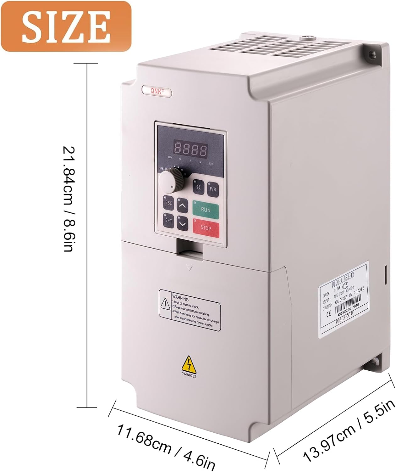
Image: Diagram showing the dimensions of the QNK VFD Converter, with measurements in centimeters and inches.
4. Setup and Installation
4.1. Wiring the VFD
Before beginning any wiring, ensure the power supply is completely disconnected. Wear appropriate personal protective gear (PPE).
- Power Input Wiring: For a 220V single-phase power supply, connect the power wires to terminals L1 and L2 on the VFD. For three-phase input, connect to L1, L2, and L3.
- Motor Output Wiring: Connect the three motor wires to terminals U, V, and W on the VFD.
- Verify Connections: After wiring, double-check that all wires are securely fastened under the correct terminals.
Video: A demonstration on how to wire the QNK VFD Converter to a motor, including connecting power input and motor output wires. It emphasizes safety precautions and checking connections.
4.2. Control Panel Overview
The VFD features a user-friendly control panel for operation and parameter adjustment. The panel can be separated for remote control.
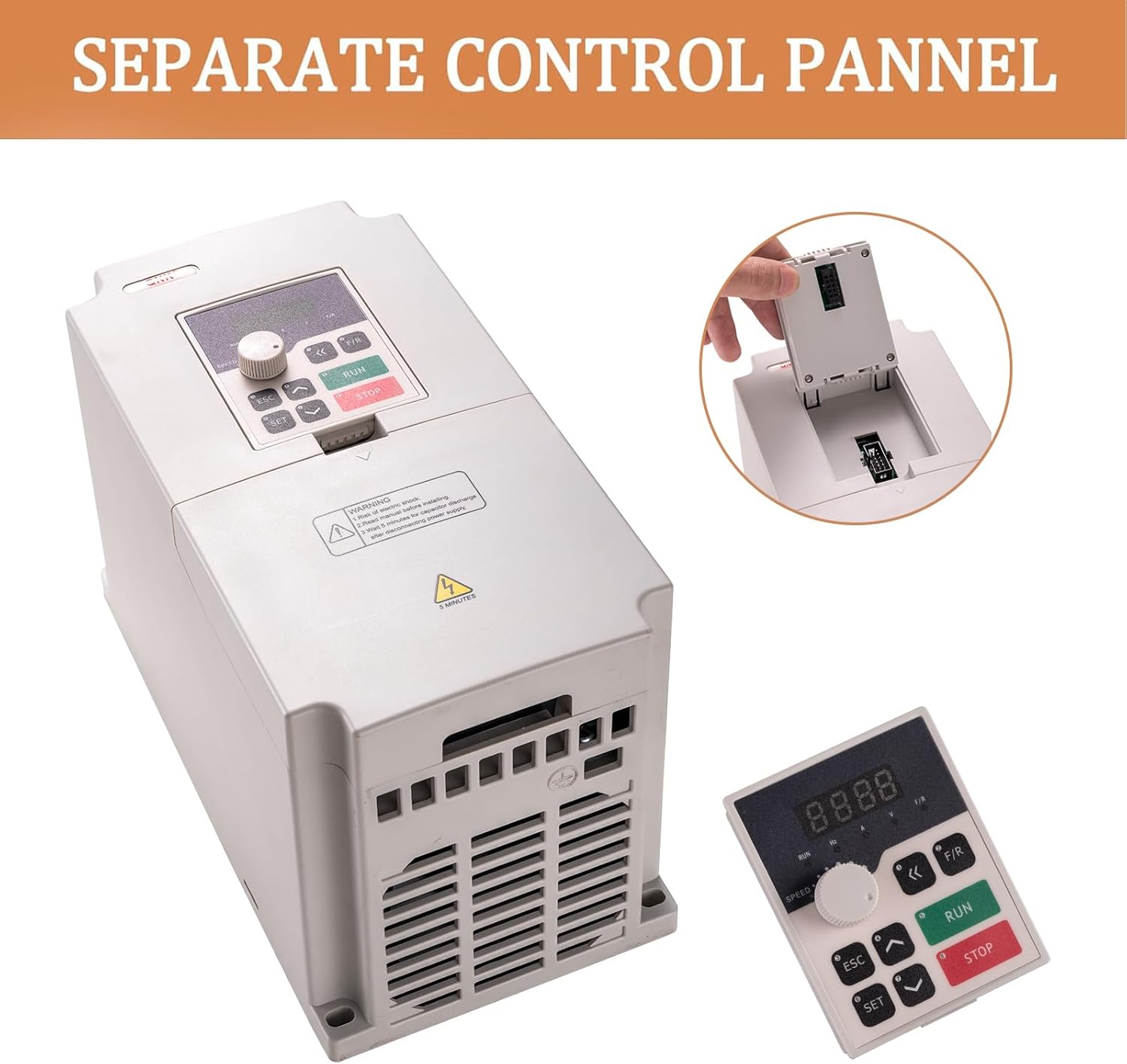
Image: The QNK VFD Converter with its detachable control panel shown separately, highlighting its modular design.
| Button/Knob | Function Description |
|---|---|
| SET | Go to the menu, or a certain parameter, and confirm the parameter. |
| ESC | Return to the previous menu or exit. |
| UP (▲) | Modify and select parameters (increase value). |
| DOWN (▼) | Modify and select parameters (decrease value). |
| SHIFT (<<) | Monitor different operation status and switch digit place. |
| F/R | Change the running direction of the motor. |
| RUN | Initiate the run command. |
| STOP | Stop command / abnormal reset command. |
| Speed Knob | Adjusts the output frequency (motor speed). |

Image: Close-up of the QNK VFD control panel, illustrating the function of each button and the speed adjustment knob.
5. Operating Instructions
5.1. Initial Power-Up and Frequency Setting
- After ensuring all wiring is correct and secure, power on the VFD.
- Turn the speed knob clockwise fully. The panel should display 50 Hz.
- Verify that the motor's rated frequency matches the inverter's rated frequency (e.g., both 50 Hz).
- If your motor drives high-torque equipment, adjust the acceleration and deceleration times to a higher value (e.g., from 10 Hz to 15 Hz or 20 Hz). This is typically done through parameter settings (e.g., F014 for acceleration time, F015 for deceleration time).
- Press the RUN button to start the motor.
5.2. Changing Motor Rotation Direction
If the motor is rotating in a reverse direction from desired, you can exchange the locations of any two wires (e.g., U and W) landing under the output terminals (U, V, and W) on the VFD. Ensure power is off before making any wiring changes.

Image: Detailed wiring diagram for the QNK VFD, showing connections for power input, motor output, and control signals. This diagram is crucial for correct installation and troubleshooting.
6. Maintenance
- Regular Cleaning: Keep the VFD clean and free from dust and debris. The multi-grid design helps prevent dust and water mist from entering the circuit board section.
- Heat Dissipation: Ensure adequate cooling space around the VFD for fast heat dissipation. The powerful cooling fan and independent air duct design contribute to efficient cooling.
- Connection Checks: Periodically inspect all wiring connections to ensure they remain tight and secure. Loose connections can lead to malfunctions or damage.
- Environmental Conditions: Operate the VFD within its specified environmental conditions (temperature, humidity) to prolong its lifespan.

Image: Illustration highlighting the powerful cooling fan and independent air duct design of the QNK VFD, crucial for maintaining optimal operating temperature.
7. Troubleshooting
If you encounter an error code or unexpected behavior, refer to the following common issues and solutions:
- Overload Protection: The VFD features protection against overload. If an overload occurs, the unit may shut down. Check the motor load and ensure it is within the VFD's capacity. Consider using a higher power VFD for heavy equipment (e.g., a 7.5 Kw VFD for a 5.5 Kw motor).
- Over/Under Voltage: The VFD has protective functions for over voltage (DC voltage > 400V) or under voltage (DC voltage < 200V). Verify the input voltage is stable and within the specified range (+/- 15%).
- Short Circuit/Stall Protection: These functions prevent damage to the VFD and motor. If activated, check for short circuits in the wiring or mechanical issues causing the motor to stall.
- Overheat Protection: Ensure proper ventilation and clear any obstructions around the VFD's cooling fan.
- Motor Not Rotating:
- Check all wiring connections for tightness and correctness.
- Verify the power supply is active.
- Ensure the motor's rated frequency matches the VFD's setting.
- If the motor is rotating in the wrong direction, exchange any two motor output wires (U, V, or W).
- General Errors: If an error code appears and you are unsure how to resolve it, or for any other product-related questions, contact QNK Customer Service.

Image: Diagram illustrating the various protection features of the QNK VFD, including overload, overheat, over-voltage, low-voltage, fuse, stall, and short circuit protection.
8. Warranty and Support
QNK is committed to providing high-quality products and customer satisfaction. For any issues or inquiries regarding your QNK VFD Converter, please contact our Customer Support Team. We aim to respond within 24 hours.
- Customer Service: Refer to your purchase documentation or the QNK official website for contact details.
- Protection Plans: Additional protection plans may be available for purchase to extend coverage beyond the standard warranty.
Ask a question about this manual
Ask about setup, troubleshooting, compatibility, parts, safety, or missing instructions. Manuals+ will review the question and use this page’s manual context to help answer it.