1. Introduction
Thank you for choosing the GAMEMAX Starlight 2 AB Mid Tower ATX PC Case. This manual provides essential information for the proper installation, operation, and maintenance of your new PC case. Please read this manual thoroughly before beginning the assembly process to ensure optimal performance and longevity of your system components.
2. Safety Information
- Always disconnect the power supply from the wall outlet before installing or removing any components.
- Handle all components with care to prevent damage.
- Wear an anti-static wrist strap to prevent electrostatic discharge (ESD) damage to sensitive components.
- Keep the case away from direct sunlight, high temperatures, and moisture.
- Ensure proper ventilation around the case to prevent overheating.
- Do not attempt to modify the case or its components, as this may void your warranty and pose a safety risk.
3. Package Contents
Please verify that all items are present in your package:
- GAMEMAX Starlight 2 AB Mid Tower ATX PC Case
- Accessory Box (containing screws, standoffs, cable ties, etc.)
- User Manual (this document)
4. Product Overview
The GAMEMAX Starlight 2 AB is a Mid Tower ATX PC case designed for efficient cooling and versatile configurations. It features a tempered glass side panel, pre-installed ARGB fans, and comprehensive hardware compatibility.
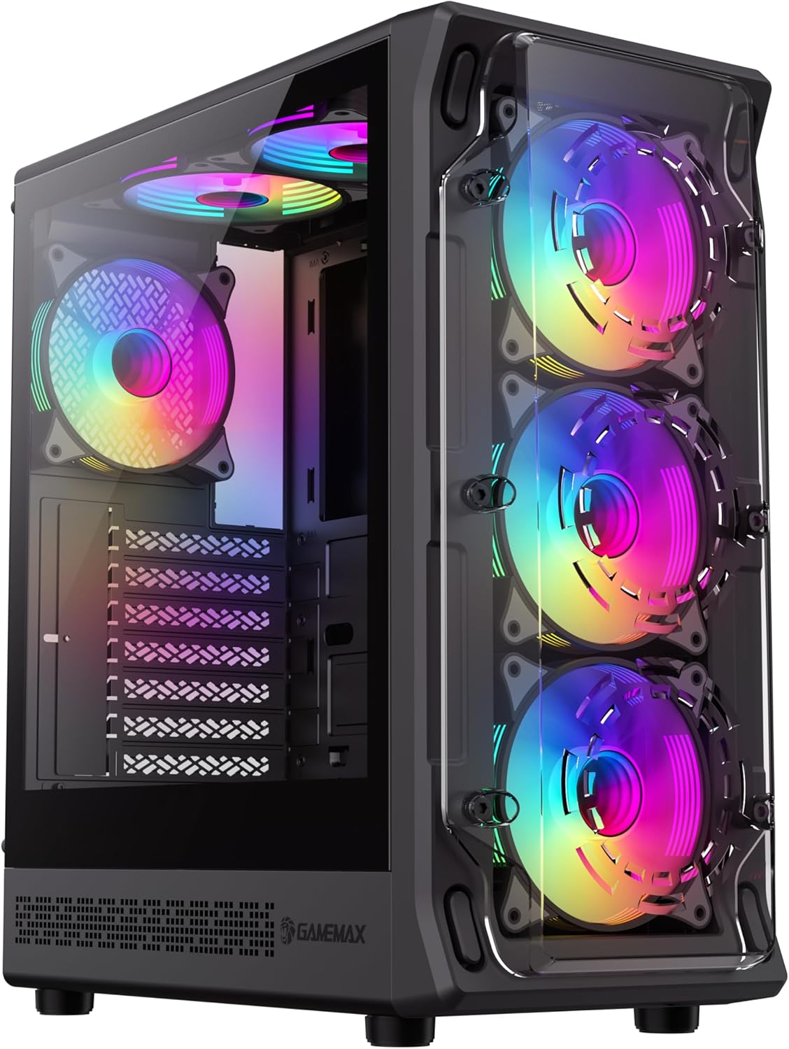
Figure 4.1: Front-left view of the GAMEMAX Starlight 2 AB PC Case, showcasing the tempered glass side panel and the vibrant ARGB lighting of the pre-installed fans.

Figure 4.2: Direct front view highlighting the three 120mm ARGB fans, visible through the clear front panel, designed for optimal airflow.
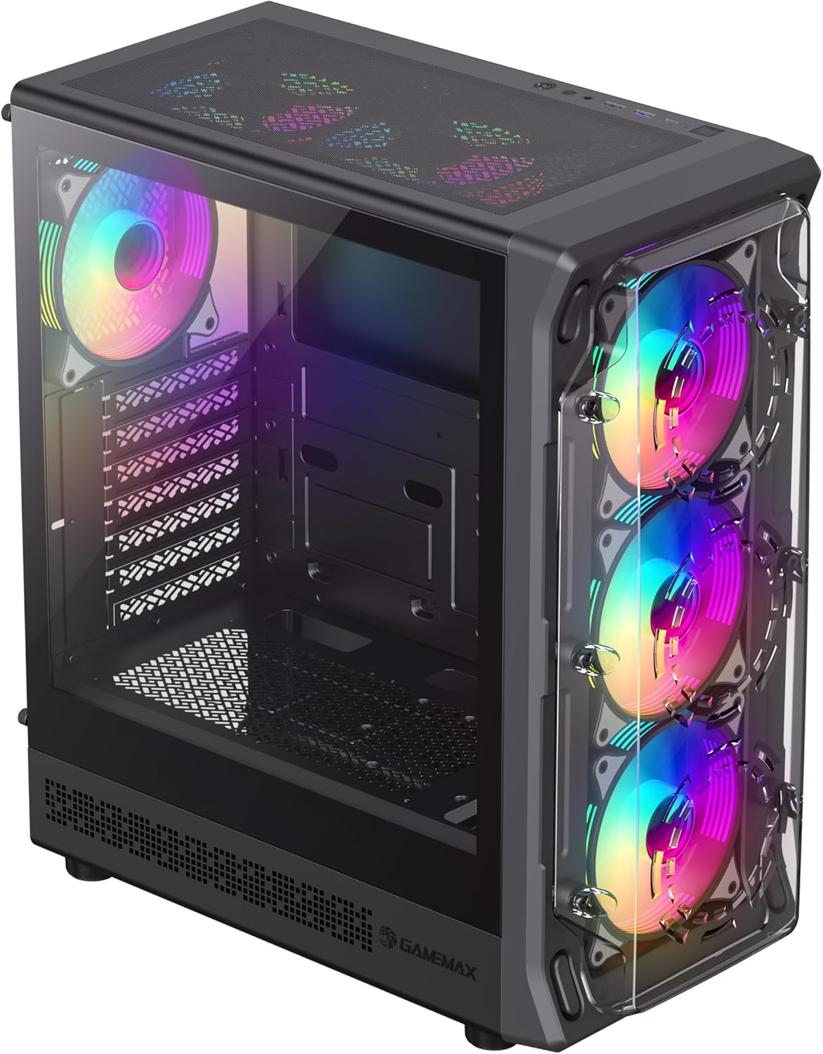
Figure 4.3: Top-front perspective showing the top-mounted I/O panel, including USB ports and audio jacks, along with the mesh top panel for additional cooling.

Figure 4.4: Rear view of the PC case, illustrating the rear exhaust fan, expansion slots, and the power supply mounting area at the bottom.

Figure 4.5: Interior view of the main chamber, showing the motherboard tray, fan mounts, and ample space for component installation.
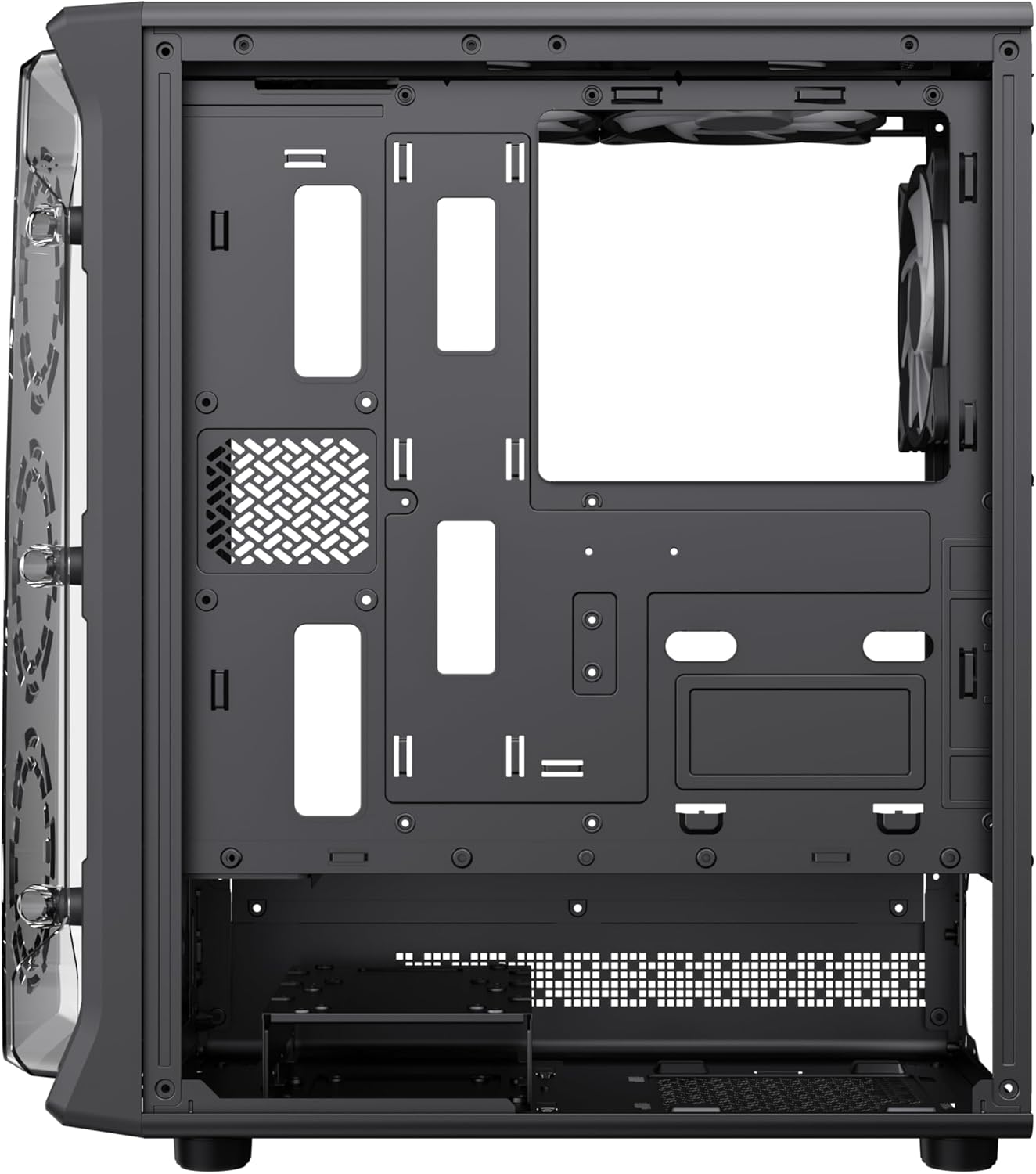
Figure 4.6: View behind the motherboard tray, revealing cable routing cutouts and mounting points for storage drives, facilitating clean cable management.
5. Specifications
| Feature | Description |
|---|---|
| Model | Starlight 2 AB |
| Case Type | Mid Tower |
| Motherboard Compatibility | ATX, Micro ATX, Mini ITX |
| Dimensions (L x W x H) | 34 x 20 x 43.6 cm |
| Weight | 4.55 kg |
| Material | Metal, Tempered Glass |
| Pre-installed Fans | 6 x 120mm ARGB Fans (3 front, 2 top, 1 rear) |
| Radiator Support | 120mm, 240mm, 360mm |
| GPU Clearance | Up to 330mm |
| CPU Cooler Height | Up to 155mm |
| I/O Ports | USB 3.0, USB 2.0, Type-C, Audio |
| Special Features | Built-In Fan, Dust Filter, RGB Lighting |
6. Setup and Installation
6.1 Preparing the Case
- Place the case on a flat, stable surface.
- Carefully remove the tempered glass side panel by unscrewing the thumb screws and sliding it open. Set it aside in a safe place.
- Remove the solid right side panel to access the cable management area.
6.2 Motherboard Installation
- Install the I/O shield into the rear opening of the case.
- Align your motherboard with the standoffs inside the case. Ensure the standoffs match your motherboard's form factor (ATX, Micro ATX, Mini ITX).
- Secure the motherboard with the provided screws.
6.3 Power Supply Unit (PSU) Installation
- Mount the PSU into the dedicated compartment at the bottom rear of the case.
- Secure the PSU with screws from the rear of the case.
6.4 Storage Device Installation (HDD/SSD)
- Locate the drive bays or mounting points for 3.5" HDDs and 2.5" SSDs.
- Install your storage devices using the appropriate screws.
6.5 Graphics Card (GPU) and Expansion Card Installation
- Remove the necessary expansion slot covers from the rear of the case.
- Insert your graphics card or other expansion cards into the PCIe slots on your motherboard.
- Secure the cards with screws.
6.6 Connecting Front I/O Cables
Connect the following cables from the case's front I/O panel to the corresponding headers on your motherboard:
- USB 3.0 Header
- USB 2.0 Header
- Type-C Header (if applicable)
- HD Audio Header
- Power Switch, Reset Switch, Power LED, HDD LED headers
6.7 Cable Management
Utilize the cable routing cutouts and tie-down points behind the motherboard tray to organize and secure cables. This improves airflow and aesthetics.
7. Operating Instructions
7.1 Powering On
After all components are installed and cables are connected, replace both side panels. Connect your power cable to the PSU and a wall outlet, then press the power button on the case's front I/O panel to start your system.
7.2 ARGB Fan Control
The pre-installed ARGB fans can be controlled via your motherboard's ARGB software (e.g., ASUS Aura Sync, MSI Mystic Light Sync, Gigabyte RGB Fusion, ASRock Polychrome Sync) if your motherboard supports a 3-pin 5V ARGB header. Connect the ARGB cable from the case's fan hub to the motherboard's ARGB header. Refer to your motherboard manual for specific instructions on ARGB software usage.
8. Maintenance
8.1 Cleaning Dust Filters
The case includes integrated removable dust filters. Regularly clean these filters to maintain optimal airflow and prevent dust buildup inside your system. Gently slide out the filters, clean them with a soft brush or rinse with water (ensure they are completely dry before reinstallation), and then reinsert them.
8.2 General Case Cleaning
Use a soft, damp cloth to wipe down the exterior surfaces of the case. For the tempered glass panel, use a glass cleaner and a microfiber cloth to avoid streaks. Avoid using harsh chemicals or abrasive materials.
9. Troubleshooting
- System does not power on: Ensure all power cables (24-pin ATX, 8-pin CPU, GPU power) are securely connected. Verify the PSU switch is in the 'ON' position. Check front panel power switch connection to the motherboard.
- Fans are not spinning or ARGB not working: Check fan power connections to the motherboard or fan hub. Ensure ARGB cables are correctly connected to a 3-pin 5V ARGB header on the motherboard. Verify ARGB software settings.
- No display output: Confirm the graphics card is properly seated in its PCIe slot and power cables are connected. Ensure the monitor cable is connected to the graphics card, not the motherboard's integrated graphics port (unless using integrated graphics).
- Overheating: Ensure all fans are spinning correctly and are oriented for proper airflow (intake/exhaust). Clean dust filters regularly. Verify CPU cooler installation.
10. Warranty and Support
For warranty information or technical support, please refer to the GAMEMAX official website or contact your local retailer. Keep your proof of purchase for warranty claims.
11. Disposal Information
Please dispose of this product in accordance with local environmental regulations. Do not dispose of electronic waste with general household waste.


