
1. Safety Information
Please read and understand all safety information before operating this multimeter. Failure to follow these instructions may result in electric shock, fire, or personal injury.
- Always ensure the multimeter is in good working condition and free from damage before use.
- Do not apply voltage or current that exceeds the maximum specified limits for the multimeter. This model supports up to 600V and 10A.
- Use caution when working with voltages above 30V AC RMS, 42V peak, or 60V DC. These voltages pose a shock hazard.
- Always connect the common (COM) test lead first, then the live test lead. Disconnect the live test lead first, then the common test lead.
- Ensure the test leads are properly seated in the correct input jacks for the measurement being performed.
- Do not use the multimeter if the test leads are damaged or if the meter casing is open.
- Replace fuses with specified types and ratings only. This device features double safety protection with 500mA/600V and 10A/600V fuses.
- Avoid using the multimeter in wet environments or during electrical storms.
- Keep fingers behind the finger guards on the test probes during measurements.
Overvoltage Category III 600V Safety Standards:
This multimeter is designed to meet CAT III 600V safety standards, providing enhanced protection against transient overvoltages in fixed installations.

Image: Internal circuit board of the DEASOMIYE T21D multimeter, highlighting the dual fuses (500mA/600V and 10A/600V) that provide anti-burn and overload protection across all ranges.
2. Product Overview
The DEASOMIYE T21D is an auto-ranging digital multimeter designed for accurate and reliable electrical measurements. It features a 6000-count True RMS display and a wide range of functions suitable for DIYers, homeowners, handymen, and electricians.

Image: The DEASOMIYE T21D Digital Multimeter, shown with its orange and black casing, large LCD display, function knob, input jacks, and included accessories such as test leads, AAA batteries, and spare safety tubes.
2.1 Key Features
- Auto-Ranging: Automatically selects the correct measurement range.
- True RMS: Provides accurate readings for non-sinusoidal AC waveforms.
- 6000 Counts Display: High-resolution digital display for precise measurements.
- Non-Contact Voltage (NCV) Detection: Safely detects AC voltage without direct contact.
- Multi-functional: Measures AC/DC Voltage, AC/DC Current, Resistance, Continuity, Frequency, Capacitance, Diode, Temperature, and Duty Cycle.
- Safety Protection: Overvoltage Category III 600V, anti-burn with double ceramic fuses.
- User-Friendly Design: Large LCD screen with backlight, data hold, support stand, test leads holder, and flashlight.
- Durable Construction: Wrapped with a sturdy, non-slip silicone protective cover.

Image: A visual representation of the DEASOMIYE T21D's multi-function capabilities, including AC/DC voltage, AC/DC current, automatic shutdown, frequency, flashlight, diode, continuity buzzer, resistance, NCV detection, duty cycle, temperature measurement, and capacitance.
2.2 Components and Display

Image: A detailed diagram labeling the key components of the DEASOMIYE T21D multimeter, including the NCV sensing area, LED display, FUNC/HZ function selection button, NCV indicator, Hold button, Function knob, COM input socket, VΩmA input socket, and 10A input socket.
- LED Display: Shows measurement readings, units, and function indicators.
- Function Knob: Used to select the desired measurement mode.
- FUNC/HZ Button: Toggles between functions within a mode (e.g., AC/DC, Frequency/Duty Cycle).
- HOLD Button: Freezes the current reading on the display.
- Backlight Button: Activates the display backlight for improved visibility in low light.
- Flashlight Button: Turns on the built-in flashlight.
- NCV Sensing Area: Detects non-contact voltage.
- Input Jacks:
- COM: Common input for all measurements (black test lead).
- VΩmA: Input for voltage, resistance, capacitance, frequency, diode, continuity, and milliampere current (red test lead).
- 10A: Input for high current measurements up to 10A (red test lead).
2.3 Packing List

Image: The complete packing list for the DEASOMIYE T21D Digital Multimeter, including the multimeter unit, test leads, 3 AAA batteries, thermocouple, safety tubes, and user manual.
The package includes:
- 1x DEASOMIYE T21D Electrical Multimeter
- 1x Probe Test Leads (Red and Black)
- 1x Thermocouple (for temperature measurement)
- 2x Safety Tubes (spare fuses)
- 3x AAA Batteries
- 1x User Manual
3. Setup
3.1 Battery Installation
- Ensure the multimeter is turned OFF.
- Locate the battery compartment on the back of the multimeter.
- Use a screwdriver to open the battery compartment cover.
- Insert three (3) AAA batteries, observing the correct polarity (+/-) as indicated inside the compartment.
- Replace the battery compartment cover and secure it with the screw.

Image: The back of the DEASOMIYE T21D multimeter, illustrating the durable case, integrated support stand, test leads holder, and the battery compartment for AAA batteries.
3.2 Connecting Test Leads
- Insert the black test lead into the COM (common) input jack.
- For most measurements (voltage, resistance, capacitance, frequency, diode, continuity, and milliampere current), insert the red test lead into the VΩmA input jack.
- For high current measurements (up to 10A), insert the red test lead into the 10A input jack.
Important:
- Always ensure test leads are securely connected before taking measurements.
- Never connect test leads to the wrong input jacks, especially when measuring current, as this can damage the multimeter or blow a fuse.
4. Operating Instructions
The DEASOMIYE T21D features an auto-ranging function, simplifying operation by automatically selecting the appropriate measurement range for most functions.

Image: The DEASOMIYE T21D multimeter with a close-up of its automatic range turntable design, indicating that it's easy to use for AC/DC readings without manual range switching.
4.1 Basic Measurement Steps
- Turn the function knob to the desired measurement mode.
- Connect the test leads to the appropriate input jacks (COM and VΩmA or 10A).
- Connect the test probes to the circuit or component under test.
- Read the measurement value on the LCD display.
- Disconnect the test probes from the circuit, then remove the test leads from the multimeter.
- Turn the function knob to the OFF position when finished.
4.2 Specific Measurement Functions
4.2.1 AC/DC Voltage Measurement
- Turn the function knob to the V~ (AC Voltage) or V- (DC Voltage) position. The multimeter will auto-range.
- Connect the black test lead to the COM jack and the red test lead to the VΩmA jack.
- Connect the test probes in parallel across the circuit or component to measure voltage.

Image: The DEASOMIYE T21D multimeter demonstrating AC voltage measurement on a power strip (displaying 223.5V AC) and DC voltage measurement on a 9V battery (displaying 9.253V DC).
4.2.2 AC/DC Current Measurement
- Turn the function knob to the mA~ (AC Current) or mA- (DC Current) position. For higher currents, use the 10A position.
- Connect the black test lead to the COM jack. Connect the red test lead to the VΩmA jack for mA measurements or the 10A jack for A measurements.
- Important: Connect the multimeter in series with the circuit to measure current. Never connect it in parallel across a voltage source when in current mode.
4.2.3 Resistance Measurement (Ω)
- Turn the function knob to the Ω position.
- Connect the black test lead to COM and the red test lead to VΩmA.
- Ensure the circuit is de-energized before measuring resistance. Connect the probes across the component.
4.2.4 Continuity Test ())))
- Turn the function knob to the Ω position and press the FUNC/HZ button until the continuity symbol ()))) appears.
- Connect the black test lead to COM and the red test lead to VΩmA.
- Connect the probes across the circuit or component. A continuous beep indicates a low-resistance path (continuity).
4.2.5 Diode Test (→|)
- Turn the function knob to the Ω position and press the FUNC/HZ button until the diode symbol (→|) appears.
- Connect the black test lead to COM and the red test lead to VΩmA.
- Connect the probes across the diode. The display will show the forward voltage drop. Reverse the probes; an open circuit reading indicates a good diode.
4.2.6 Capacitance Measurement (C)
- Turn the function knob to the C position.
- Connect the black test lead to COM and the red test lead to VΩmA.
- Ensure the capacitor is fully discharged before testing. Connect the probes across the capacitor.
4.2.7 Frequency (Hz) and Duty Cycle (%)
- Turn the function knob to the Hz% position.
- Connect the black test lead to COM and the red test lead to VΩmA.
- Connect the probes to the signal source. Press FUNC/HZ to toggle between Frequency (Hz) and Duty Cycle (%).
4.2.8 Temperature Measurement (°C/°F)
- Turn the function knob to the °C/°F position.
- Insert the thermocouple into the VΩmA and COM jacks, observing polarity.
- Place the thermocouple tip on or near the object whose temperature is to be measured. Press FUNC/HZ to switch between Celsius and Fahrenheit.

Image: The DEASOMIYE T21D multimeter displaying a temperature reading (26.08°C) while a thermocouple, connected to the meter, is immersed in a glass of water.
4.2.9 Non-Contact Voltage (NCV) Detection
- Turn the function knob to the NCV position.
- Move the NCV sensing area (top of the multimeter) close to a live AC voltage source (e.g., an outlet or insulated wire).
- The multimeter will emit an audible beep and the NCV indicator will light up, with increasing frequency as it gets closer to the voltage source.
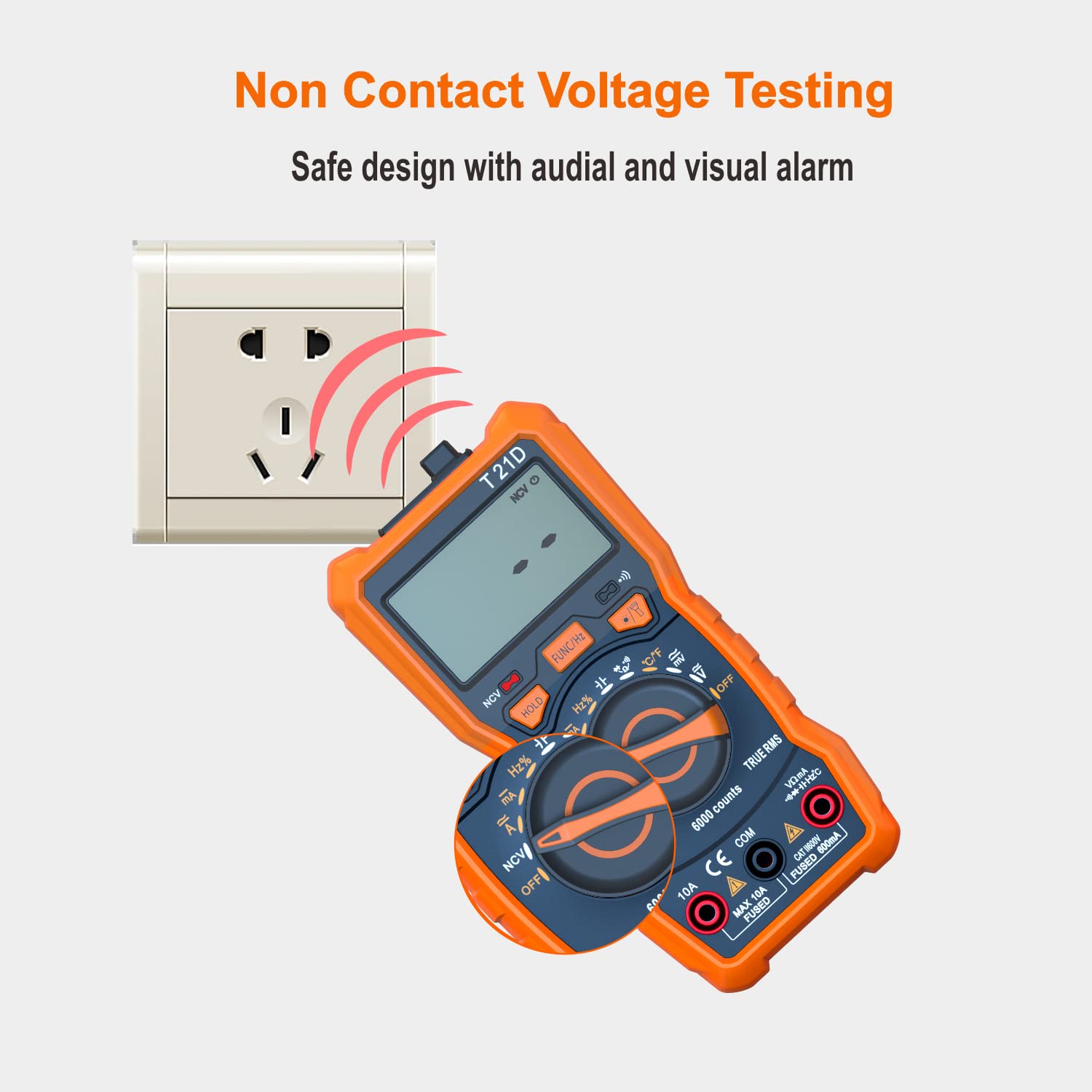
Image: The DEASOMIYE T21D multimeter detecting non-contact voltage near an electrical outlet, indicated by red arcs representing the detection field and the NCV symbol on the display.
4.3 Special Functions
4.3.1 Data Hold
Press the HOLD button to freeze the current reading on the display. Press it again to release the hold function.
4.3.2 Backlight
Press the backlight button (often combined with the flashlight button) to turn on the display backlight. This improves visibility in dimly lit areas. Press again to turn off.

Image: The DEASOMIYE T21D multimeter with its LCD display illuminated by a backlight, showing a clear reading in a low-light setting.
4.3.3 Flashlight
Press the flashlight button (often combined with the backlight button) to activate the built-in flashlight. This helps illuminate the work area. Press again to turn off.

Image: The DEASOMIYE T21D multimeter with its integrated flashlight turned on, illuminating a dark electrical panel, demonstrating its utility in low-light conditions.
5. Maintenance
Proper maintenance ensures the longevity and accuracy of your DEASOMIYE T21D multimeter.
5.1 Cleaning
- Wipe the meter casing with a damp cloth and mild detergent. Do not use abrasives or solvents.
- Keep the display clean and free from dust.
5.2 Battery Replacement
When the battery indicator appears on the display, replace the batteries promptly to ensure accurate readings. Refer to Section 3.1 for battery installation instructions.
5.3 Fuse Replacement
If the multimeter fails to measure current or shows an 'OL' (Overload) reading when measuring current, the fuse may be blown. This multimeter uses two fuses:
- F1: 500mA/600V fast-acting fuse for the VΩmA input.
- F2: 10A/600V fast-acting fuse for the 10A input.
To replace a fuse:
- Ensure the multimeter is turned OFF and all test leads are disconnected.
- Open the battery compartment cover on the back of the multimeter.
- Carefully remove the old fuse(s).
- Replace with new fuses of the exact specified type and rating. Using incorrect fuses can compromise safety and damage the meter.
- Securely close the battery compartment cover.

Image: The DEASOMIYE T21D multimeter with test leads connected to an electrical panel, illustrating its intelligent double protection feature with built-in 500mA/600V and 10A/600V explosion-proof fuse tubes for enhanced safety and reliability.
6. Troubleshooting
If you encounter issues with your DEASOMIYE T21D multimeter, refer to the following common troubleshooting tips:
- No Display/Faint Display: Check battery installation and replace batteries if low.
- 'OL' (Overload) Reading: The measured value exceeds the selected range (if not in auto-ranging) or the maximum input limit. Ensure the correct function and input jacks are selected. For current measurements, a blown fuse may be indicated.
- Incorrect Readings:
- Ensure test leads are fully inserted and not damaged.
- Verify the correct function mode is selected for the measurement.
- Check for proper connection to the circuit (series for current, parallel for voltage).
- For resistance/continuity, ensure the circuit is de-energized.
- No Continuity Beep: Check if the continuity function is active (continuity symbol on display). Ensure good contact with the circuit.
- NCV Not Detecting: Ensure the NCV function is selected and the sensing area is close enough to a live AC voltage source.
If problems persist, contact customer support for assistance.
7. Specifications
| Parameter | Value |
|---|---|
| Model Number | T21D |
| Display | 6000 Counts, True RMS |
| AC/DC Voltage | Up to 600V |
| AC/DC Current | Up to 10A |
| Resistance | Yes |
| Capacitance | Yes |
| Frequency | Yes |
| Temperature | Yes (-20°C to 1000°C / -4°F to 1832°F) |
| Diode Test | Yes |
| Continuity Test | Yes |
| NCV (Non-Contact Voltage) | Yes |
| Duty Cycle | Yes |
| Power Source | 3x AAA Batteries (included) |
| Safety Rating | CAT III 600V |
| Product Dimensions | 2.68 x 5.51 x 1.69 inches |
| Item Weight | 10.58 ounces (300 Grams) |
| Color | Orange and Black |

Image: A visual comparison showing the DEASOMIYE T21D's 6000-count display offering a more accurate and higher resolution reading compared to a standard 2000-count display.
8. Warranty and Support
DEASOMIYE provides a 30-day manufacturer's guarantee for this product. Additionally, lifetime customer support is available to assist with any questions or issues you may encounter.
For support, please contact DEASOMIYE customer service. You can typically find contact information on the product packaging or the official DEASOMIYE website.