1. Introduction
This manual provides detailed instructions for the installation, operation, and maintenance of the Mechanivis CWT-TM-32DS Temperature Acquisition Module. This module is designed for industrial applications requiring precise temperature monitoring and data acquisition using 18B20 sensors and RS485 Modbus communication.
Key Features:
- Accurate Measurement: High resolution and high accuracy for reliable temperature readings.
- High Compatibility: Supports a wide range of 18B20 temperature sensors.
- Variety of Outputs: Utilizes RS485 (Modbus RTU) for data transmission.
- Industrial Adaptability: Suitable for use in harsh industrial environments.
- Signal Conversion: Converts analog sensor signals to digital for easy data acquisition and transmission.
2. Safety Information
Please read and understand all safety instructions before installing or operating the module. Failure to follow these instructions may result in equipment damage or personal injury.
- Ensure the power supply voltage is within the specified range (DC 8-30V).
- Disconnect power before making any wiring connections.
- Avoid exposing the module to moisture, extreme temperatures, or corrosive environments.
- Only qualified personnel should perform installation and maintenance.
3. Product Overview
The CWT-TM-32DS is a compact temperature acquisition module featuring 32 channels for 18B20 sensors and an RS485 Modbus RTU output. It is designed for easy integration into industrial control systems.
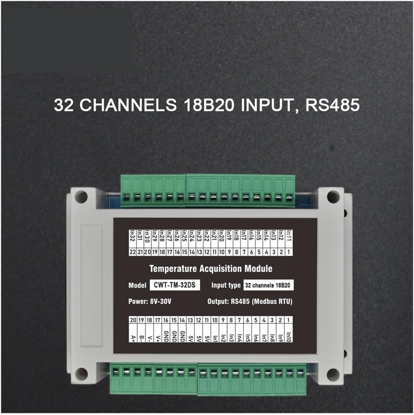
Figure 3.1: Front view of the CWT-TM-32DS module, highlighting the 32 input channels, RS485 output, model designation, and power requirements.

Figure 3.2: Side view of the CWT-TM-32DS module, illustrating the accessible green terminal blocks for wiring connections.
4. Package Contents
The standard package for the CWT-TM-32DS module includes:
- 1 x Mechanivis CWT-TM-32DS Temperature Acquisition Module
Note: 18B20 temperature sensors and RS485 communication cables are sold separately.
5. Setup
5.1 Mounting
The CWT-TM-32DS module is designed for 35mm DIN-rail mounting, allowing for secure and organized installation within industrial control cabinets.

Figure 5.1: Back view of the CWT-TM-32DS module, showing the integrated red clips for 35mm DIN-rail mounting.
5.2 Wiring Connections
Ensure all power is disconnected before making any wiring connections. Refer to the terminal descriptions below for correct wiring.
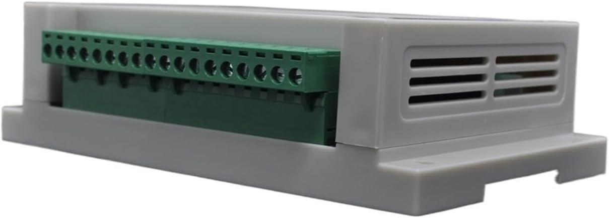
Figure 5.2: Terminal descriptions for wiring the CWT-TM-32DS module.
5.2.1 Power Supply Connection
- Connect the positive lead of your DC 8-30V power supply to the +V terminal.
- Connect the negative lead (ground) of your power supply to the GND terminal.
5.2.2 18B20 Sensor Connections
Each 18B20 sensor requires three connections: power, data, and ground. The module provides dedicated terminals for these.
- Connect the 18B20 sensor's power line to the Vout terminal.
- Connect the 18B20 sensor's data line to the corresponding INx terminal (e.g., IN1, IN2, etc.).
- Connect the 18B20 sensor's ground line to the GND terminal.
5.2.3 RS485 Communication Connection
Connect the module to your RS485 network using a twisted-pair cable.
- Connect the RS485 A (D+) line to the A (D+) terminal.
- Connect the RS485 B (D-) line to the B (D-) terminal.
6. Operation
The CWT-TM-32DS module communicates using the Modbus RTU protocol over RS485. This section details how to configure communication parameters and read temperature data.
6.1 Modbus Communication Parameters
The module's communication parameters (baud rate, parity, and device address) can be configured via Modbus registers. The initial values are typically set to a default, but can be changed as needed.

Figure 6.1: Modbus register map for configuring communication parameters and device address.
Address 10 (hex): Communication Parameters
- Byte Order LO: Controls parity and baud rate.
- BIT[4:3]: 00=none, 01=even, 10=odd (parity)
- BIT[2:0]: 000=9600, 001=1200, 010=2400, 011=4800, 100=9600, 101=14400, 110=19200 (baud rate)
- Byte Order HI: Sets the device address (1-250).
6.2 Data Acquisition (Reading Temperature)
Temperature data from each of the 32 channels can be read from specific Modbus holding registers. The data is typically in UINT format with a scale factor of 0.1, meaning the raw value read should be multiplied by 0.1 to get the actual temperature in degrees Celsius.

Figure 6.2: Modbus register map for reading temperature data from channels 1 through 21.
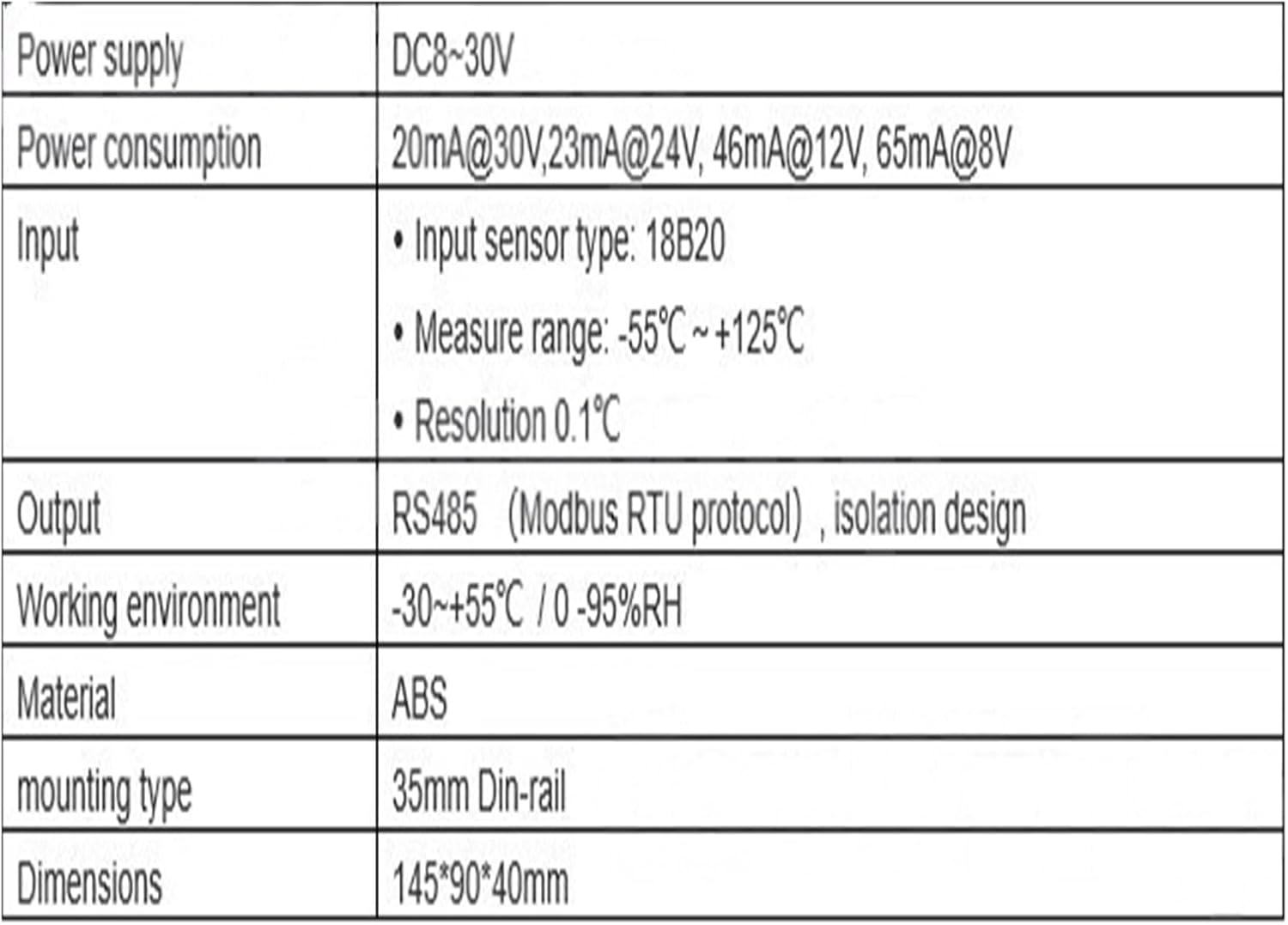
Figure 6.3: Modbus register map for reading temperature data from channels 22 through 32.
To read temperature data:
- Send a Modbus RTU read holding registers command to the module's address.
- Specify the starting register address (e.g., 20H for Channel 1) and the number of registers to read.
- The module will respond with the raw UINT values.
- Divide the raw value by 10 (or multiply by 0.1) to obtain the temperature in degrees Celsius.
7. Specifications
The following table details the technical specifications of the CWT-TM-32DS module:

Figure 7.1: Detailed technical specifications of the CWT-TM-32DS module.
| Parameter | Value |
|---|---|
| Power Supply | DC 8-30V |
| Power Consumption | 20mA@30V, 23mA@24V, 46mA@12V, 65mA@8V |
| Input Sensor Type | 18B20 |
| Measure Range | -55°C ~ +125°C |
| Resolution | 0.1°C |
| Output | RS485 (Modbus RTU protocol), isolation design |
| Working Environment | -30 ~ +55°C / 0-95%RH (non-condensing) |
| Material | ABS |
| Mounting Type | 35mm DIN-rail |
| Dimensions | 145mm * 90mm * 40mm |
| Package Dimensions | 1.18 x 0.79 x 0.39 inches |
| Item Weight | 6.61 pounds |
8. Troubleshooting
If you encounter issues with your CWT-TM-32DS module, consider the following common troubleshooting steps:
- No Power: Verify that the power supply is connected correctly to the +V and GND terminals and that the voltage is within the 8-30V DC range. Check for loose connections.
- No Communication:
- Ensure RS485 A(D+) and B(D-) lines are connected correctly (A to A, B to B).
- Check that the Modbus device address, baud rate, and parity settings on your master device match those configured on the CWT-TM-32DS module.
- Verify the RS485 network cabling for continuity and proper termination (if required by your network setup).
- Incorrect Temperature Readings:
- Ensure 18B20 sensors are correctly wired to Vout, INx, and GND terminals.
- Check the integrity of the 18B20 sensors and their cables.
- Confirm that the software reading the Modbus registers is applying the correct scale factor (0.1) to the raw data.
9. Maintenance
The CWT-TM-32DS module is designed for low maintenance. Follow these guidelines to ensure optimal performance:
- Keep the module clean and free from dust and debris. Use a soft, dry cloth for cleaning.
- Ensure the operating environment remains within the specified temperature and humidity ranges.
- Regularly inspect wiring connections for tightness and signs of wear or corrosion.
10. Warranty and Support
For warranty information or technical support, please contact your vendor or the manufacturer directly. Provide your product model number (CWT-TM-32DS) and a detailed description of the issue when seeking assistance.


