1. Introduction and Overview
The DEWENWILS PTM01 is a heavy-duty 24-hour mechanical timer switch designed for automatic control of various electrical appliances. It features a robust metal enclosure, is weatherproof, and is suitable for both indoor and outdoor applications. This timer is ideal for managing devices such as pool pumps, water heaters, lights, and fans, offering reliable scheduling with its mechanical dial.
Key features include:
- Automatic 24-hour control with up to two ON/OFF programs daily.
- High power load capacity: Max 40A, 120V, 2HP motor.
- Simplified wiring for easier installation.
- Weatherproof NEMA-3R metal enclosure with IP44 rating.
- ETL certified for safety and reliability.
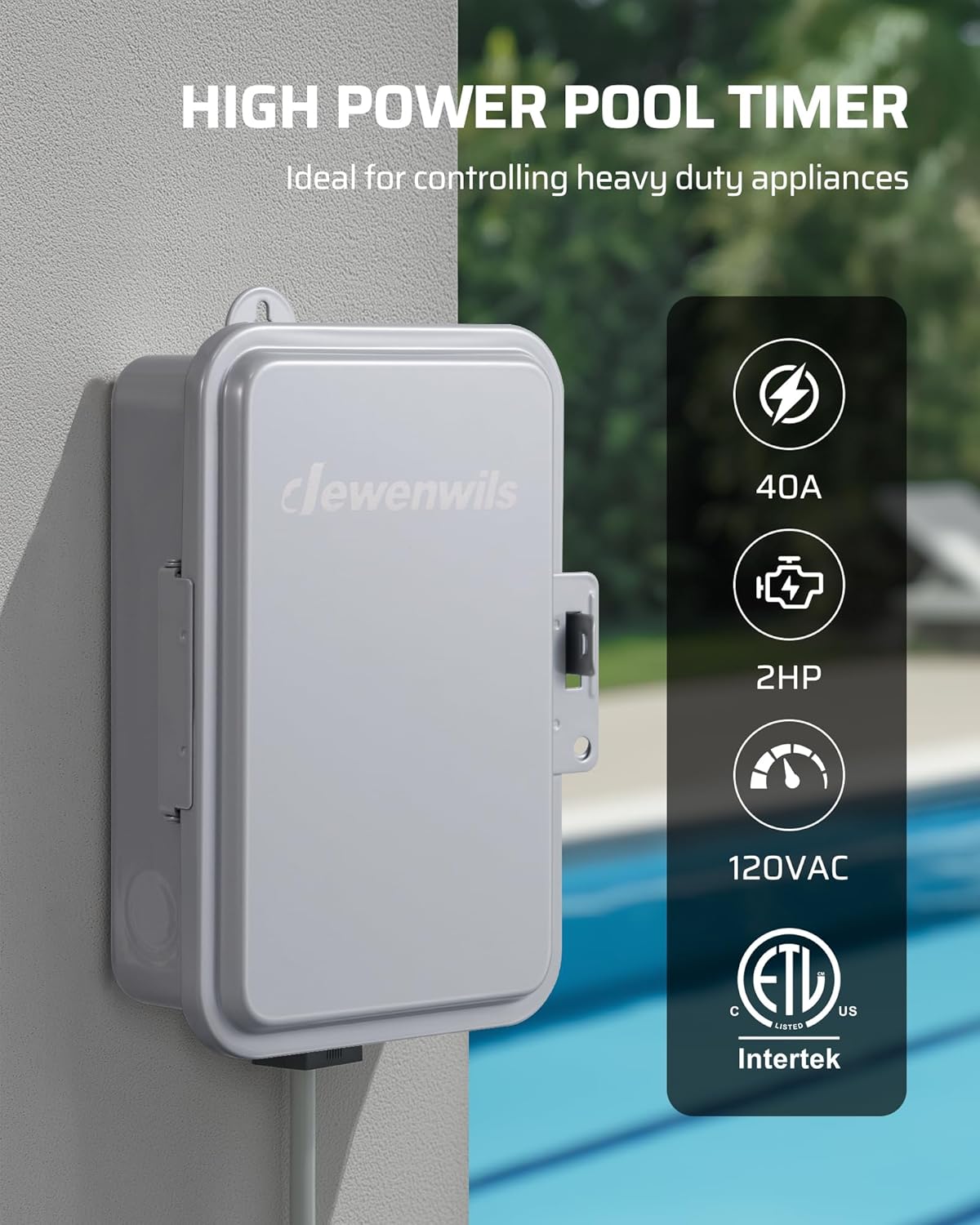
Image 1.1: The DEWENWILS PTM01 Mechanical Timer Switch, showcasing its robust design and suitability for heavy-duty applications.
2. Safety Information
Please read and understand all instructions before installing or operating this device. Failure to follow these instructions may result in electric shock, fire, or serious injury.
- WARNING: Risk of electric shock. Installation should be performed by a qualified electrician or service personnel.
- Always disconnect power at the circuit breaker or fuse box before installing or servicing the timer.
- Ensure all wiring connections are secure and comply with local electrical codes.
- Do not exceed the maximum load ratings of 40A, 120VAC, 2HP.
- This timer is designed for 120VAC applications only. Do not use with 240VAC systems.
- Keep the enclosure door closed and latched to maintain its weatherproof rating.
- Use copper conductors only.
3. Package Contents
Verify that all components are present before beginning installation:
- DEWENWILS PTM01 Mechanical Timer Switch Unit
- Installation Manual (this document)
- Mounting Hardware (screws, anchors)
- ON/OFF Trippers (pre-installed or included separately)
4. Product Features
- 24-Hour Mechanical Dial: Allows for setting up to two ON/OFF cycles within a 24-hour period, which repeat daily.
- Heavy-Duty Capacity: Supports a maximum load of 40 Amps at 120 Volts AC, suitable for motors up to 2 Horsepower.
- Weatherproof Enclosure: Constructed with a NEMA-3R rated metal enclosure and IP44 waterproof protection, ensuring durability in harsh outdoor conditions (operating temperature range: -40°F to 140°F).
- Manual Override Switch: Provides immediate ON/OFF control without affecting the programmed schedule.
- Easy Wiring: Designed with clear internal layout and wiring guides to simplify installation.
- ETL Certified: Ensures the product meets recognized safety standards.

Image 4.1: The timer's weatherproof design, suitable for outdoor installation in various weather conditions.
5. Specifications
| Model Number | PTM01 |
| Input Voltage | 120VAC, 60Hz |
| Switch Type | SPST (Single Pole Single Throw) |
| Max Load | 40A Resistive, 2HP (120VAC) |
| Enclosure Rating | NEMA-3R, IP44 Weatherproof |
| Operating Temperature | -40°F to 140°F (-40°C to 60°C) |
| Material | Metal |
| Dimensions | 4.72"D x 6.69"W x 7.87"H |
| Certifications | ETL Listed |
6. Installation
IMPORTANT: All wiring must comply with national and local electrical codes. Installation should be performed by a qualified electrician. Ensure power is disconnected at the main panel before beginning installation.
6.1 Mounting the Timer Box
- Choose a suitable location for mounting the timer box. It should be easily accessible and protected from direct impact.
- Use the provided mounting hardware to securely attach the timer box to a wall or sturdy surface. Ensure the box is level.
6.2 Wiring Instructions
The PTM01 timer box is designed for straightforward wiring. Refer to the internal wiring diagram and the images below for guidance. This timer supports controlling one or two 120VAC loads simultaneously.
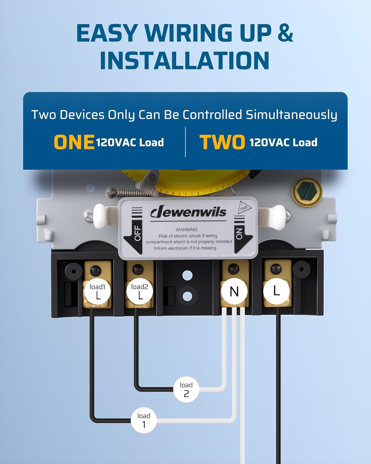
Image 6.1: Simplified wiring diagram for connecting one or two 120VAC loads to the timer switch.

Image 6.2: Internal view of the timer box, showing the mechanical dial, manual override switch, and clearly labeled wiring terminals.
- Power Input: Connect the incoming 120VAC Line (L) and Neutral (N) wires to the designated "Power L" and "Power N" terminals.
- Load Output (One Device):
- Connect the load's Line wire to the "Load L" terminal.
- Connect the load's Neutral wire to the "Load N" terminal.
- Load Output (Two Devices):
- For Load 1: Connect its Line wire to "Load1 L" and its Neutral wire to "Load1 N".
- For Load 2: Connect its Line wire to "Load2 L" and its Neutral wire to "Load2 N".
- Ensure all connections are tight and secure.
- After wiring, close and latch the enclosure door to maintain its weatherproof integrity.
7. Operating Instructions
7.1 Setting the Current Time
- Open the timer box door.
- Gently rotate the yellow mechanical dial clockwise until the current time aligns with the "TIME" arrow indicator on the inner housing. The dial is marked with 24 hours (1-12 AM, 1-12 PM).
- No tools are required for this adjustment.

Image 7.1: Detailed view of the mechanical dial, showing the current time indicator and the ON/OFF trippers.
7.2 Programming ON/OFF Cycles
The timer comes with two sets of trippers: a white tripper for ON and a black tripper for OFF. These trippers are inserted into the slots around the edge of the yellow dial.
- Set ON Time: Insert a white tripper into the slot corresponding to the desired ON time.
- Set OFF Time: Insert a black tripper into the slot corresponding to the desired OFF time.
- You can set up to two ON/OFF cycles per 24-hour period. Ensure that an ON tripper is followed by an OFF tripper for each cycle.
- Once set, the timer will automatically repeat these cycles daily.

Image 7.2: Visual example of setting ON/OFF times for a fountain, illustrating the daily cycle.
7.3 Manual Override
The timer features a manual override switch located below the dial. This switch allows you to temporarily turn the connected device ON or OFF without altering the programmed schedule.
- Slide the switch to "ON" to keep the device continuously ON, overriding the schedule.
- Slide the switch to "OFF" to keep the device continuously OFF, overriding the schedule.
- Slide the switch to "AUTO" (center position) to resume the programmed schedule.

Image 7.3: Explanation of the manual override switch positions and their functions.
8. Maintenance
- Cleaning: Periodically wipe the exterior of the timer box with a damp cloth. Do not use abrasive cleaners or solvents. Ensure the door seal is free of debris.
- Inspection: Regularly check the timer box for any signs of damage, corrosion, or loose connections. Ensure the door latch is functioning correctly to maintain weatherproof integrity.
- No User-Serviceable Parts: The internal mechanism of the timer is not user-serviceable. Do not attempt to open or repair the internal components.
9. Troubleshooting
| Problem | Possible Cause | Solution |
|---|---|---|
| Device does not turn ON/OFF at programmed times. |
|
|
| Device is always ON or always OFF. | Manual override switch is engaged. | Set the manual override switch to "AUTO" to resume programmed operation. |
| No power to the connected device. |
|
|
10. Official Product Video
Video 10.1: An official product video demonstrating the features and operation of the DEWENWILS PTM01 24-Hour Mechanical Timer Switch, including its weatherproof design and ease of setting.
11. Warranty and Support
For warranty information or technical support, please refer to the warranty card included with your product or contact DEWENWILS customer service directly. Contact details can typically be found on the manufacturer's official website or on the product packaging.


