
1. Introduction
The VIHELM HT5910 is a multi-functional digital instrument designed for comprehensive electrical testing, including RCD (Residual Current Device) testing, loop impedance testing, resistance measurement, voltage measurement, and megohmmeter functions. This manual provides essential information for the safe and effective operation, maintenance, and troubleshooting of your HT5910 device.
2. Safety Information
Always adhere to local and national safety regulations when performing electrical measurements. Failure to follow safety precautions can result in electric shock, injury, or damage to the instrument. This device is rated for CAT III 1000V and CAT IV 600V environments.
- Ensure the instrument is in good working condition before use.
- Do not use the instrument if it appears damaged or if the test leads are compromised.
- Always disconnect power to the circuit before connecting or disconnecting test leads, unless specifically instructed otherwise for a particular test.
- Wear appropriate personal protective equipment (PPE), such as insulated gloves and safety glasses.
- Do not operate the instrument in wet conditions or explosive atmospheres.
- Refer to the "Input Voltage Indication" section for warnings regarding high voltage.
3. Package Contents
Verify that all items listed below are present in your package:
- HT5910 RCD/Loop Tester (x1)
- USB Cable (x1)
- Test Line (x1 set)
- English Manual (x1)
- Test Clips (x3)
- Protection Bag (x1)
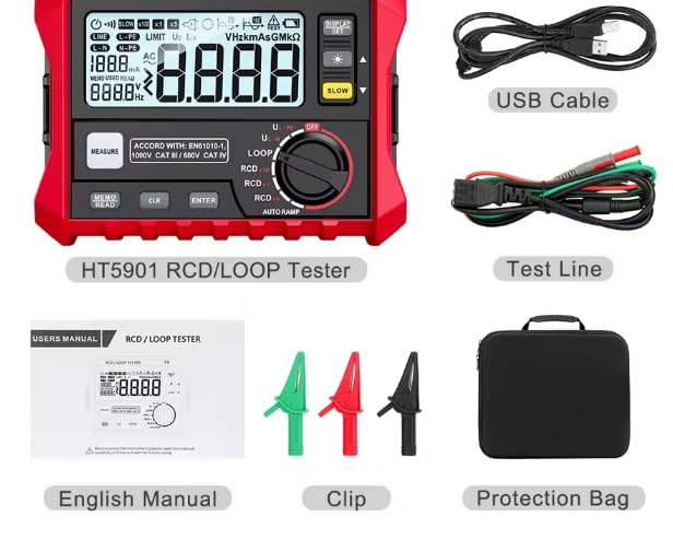
Figure 3.1: Contents of the HT5910 package, including the tester, USB cable, test leads, manual, clips, and carrying bag.
4. Product Overview
4.1 Device Layout
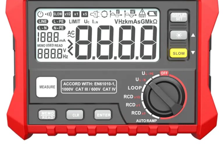
Figure 4.1: Front view of the HT5910 tester, showing the LCD display, function knob, and control buttons.
The HT5910 features a large LCD digital display for clear readings, a rotary function knob for mode selection, and various push-buttons for measurement control, data storage, and display settings.
4.2 Panel Function Description
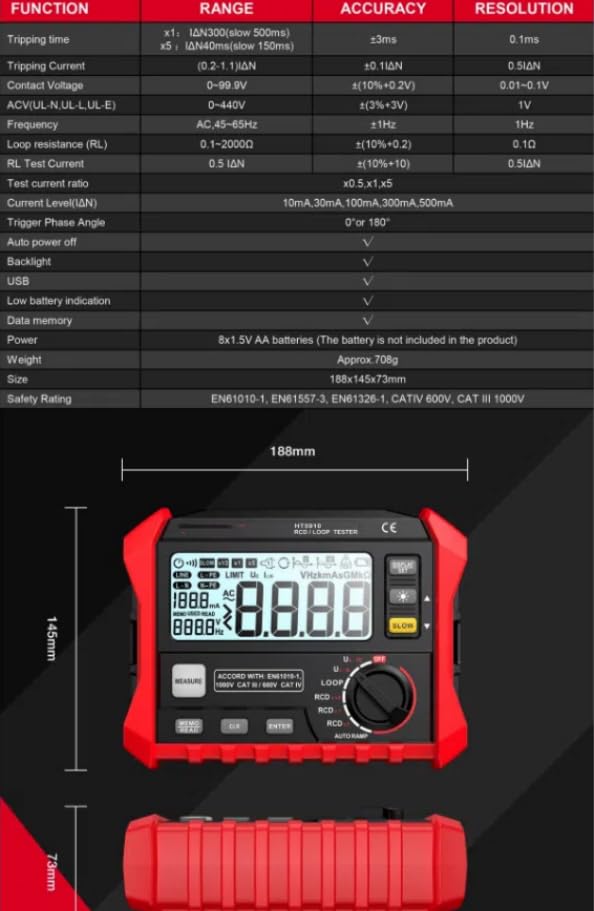
Figure 4.2: Labeled diagram illustrating the functions of each button, key, and port on the HT5910.
- AC IN: Test terminals for connecting leads.
- USB Port: Used to connect the tester to a PC for data transfer.
- Display Screen: Shows measurement values, units, and status indicators.
- Display/Set Key: For adjusting display settings.
- Backlight Key: Activates or deactivates the display backlight.
- Previous/Backward Search Key: Used for navigating stored data.
- SLOW Key: Adjusts measurement speed or other parameters.
- Function Knob: Rotary switch to select measurement modes (LOOP, RCD x1/2, RCD x1, RCD x5, AUTO RAMP).
- Measurement Key: Initiates a measurement.
- Memo/Read Key: Stores current measurement data or recalls stored data.
- Clear Key: Clears data or settings.
- Enter Key: Confirms selections or actions.
4.3 Display Screen Content Description

Figure 4.3: Detailed view of the HT5910 LCD display, explaining various icons and indicators.
The LCD displays various information, including:
- Measurement Value: The primary numerical result of the test.
- Measurement Unit: V, Hz, kA, Ω, GΩ, MΩ, etc.
- Mode Indicators: LINE, L-PE, L-N, N-PE for connection types.
- RCD Multiplier: x1/2, x1, x5 for RCD testing.
- Limit Indicator: Shows set limits for tests.
- Battery Level Indication: Displays remaining battery power.
- Memory Status: "MEMO USED READ" indicates data storage/recall.
- Auto Power Off: Icon indicating automatic shutdown feature.
- Alarm Prompt: Visual warning for certain conditions.
- Excessive Range: Indication when measurement exceeds the instrument's range.
4.4 Key Features
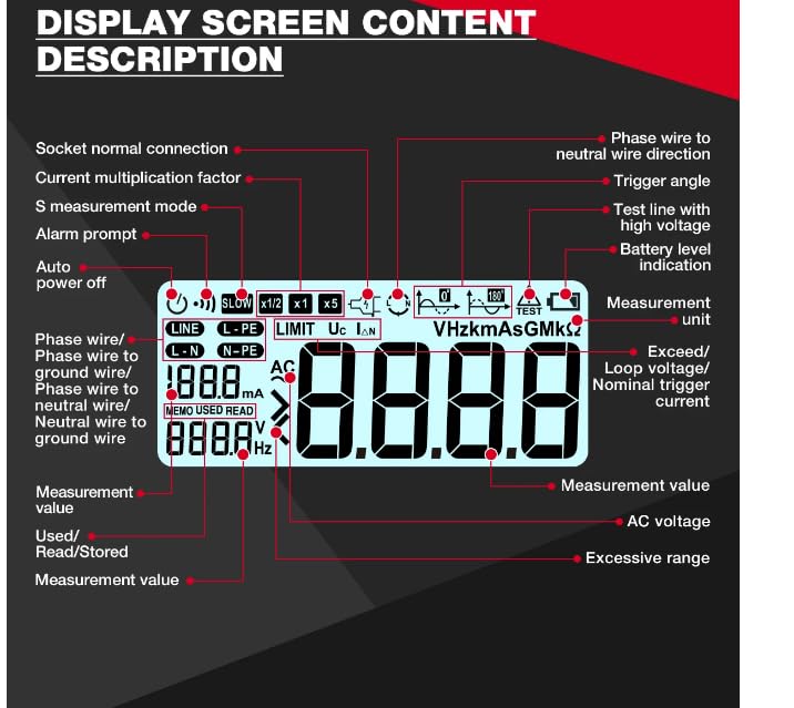
Figure 4.4: Overview of key features including the high-definition backlit display, data storage capability, and input terminal design.
- High-Definition Backlit Digital Display: Ensures clear readability of measurement data even in low-light conditions.
- Measurement Data Storage: Capable of storing up to 1000 sets of measurement data for later review or transfer.
- Input Terminal Design: Features clearly labeled AC IN test terminals and a USB port for PC connection.
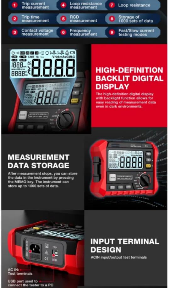
Figure 4.5: Additional features including the robust rubber protective cover, input voltage indication, low battery warning, and L-N voltage measurement.
- Rubber Protective Cover Design: The PVC rubber cover provides shock resistance, abrasion resistance, and durability, ensuring long-lasting protection for the instrument.
- Input Voltage Indication: When the AC input voltage exceeds 440V during measurement, the display will show ">>440V". If the input voltage exceeds 30V, a warning symbol will appear, indicating the need for caution.
- Low Battery Voltage Warning: A battery symbol will be displayed on the upper right corner of the screen when the instrument's battery voltage is low, indicating that battery replacement is needed.
- L-N Fire-Wire to Zero Voltage Measurement: Capability to measure voltage between live and neutral wires.

Figure 4.6: Features such as L-PE voltage measurement, automatic power-off function, and the battery compartment.
- L-PE Fire-Wire to Ground Voltage Measurement: Capability to measure voltage between live and protective earth wires.
- Auto Power Off: The instrument will automatically shut down after 10 minutes of inactivity to conserve battery life. To resume operation, rotate the function knob to the OFF position, wait 5 seconds, then select the desired mode.
- Battery Compartment: Houses 8x1.5V AA batteries (not included).
5. Setup
5.1 Battery Installation
- Ensure the instrument is powered off.
- Locate the battery compartment on the rear of the device.
- Open the battery compartment cover.
- Insert 8x1.5V AA batteries, observing correct polarity (+/-).
- Close the battery compartment cover securely.
Note: Batteries are not included with the product.
5.2 Connecting Test Leads
- Identify the AC IN test terminals on the top of the instrument.
- Connect the provided test leads firmly into the appropriate terminals. Ensure a secure connection to prevent inaccurate readings or safety hazards.
- Attach the test clips to the test leads as needed for your specific measurement application.
6. Operating Instructions
6.1 Powering On/Off
- To power on, rotate the Function Knob from the "OFF" position to any desired measurement mode (e.g., LOOP, RCD x1).
- To power off, rotate the Function Knob to the "OFF" position.
6.2 Selecting Measurement Mode
Use the large rotary Function Knob to select the desired test mode. Available modes include:
- LOOP: For loop impedance testing.
- RCD x1/2, RCD x1, RCD x5: For RCD tripping time and current tests at different multipliers of the nominal RCD current (IΔN).
- AUTO RAMP: For automatic ramp testing of RCDs.
6.3 Performing a Measurement
- Select the appropriate measurement mode using the Function Knob.
- Connect the test leads to the circuit under test according to the specific test requirements (e.g., L-N, L-PE).
- Press the MEASURE key to initiate the test.
- Observe the readings on the LCD display.
- For RCD tests, note the tripping time and current.
6.4 Data Storage and Recall
- Storing Data: After a measurement is complete, press the MEMO/READ key to store the current data set. The instrument can store up to 1000 sets of data.
- Recalling Data: In a measurement mode, press the MEMO/READ key to enter data recall mode. Use the Previous/Backward Search keys to navigate through stored records.
- Clearing Data: Press the CLR key to clear specific data or settings as prompted by the display.
6.5 PC Connection
To transfer stored data to a computer:
- Connect the HT5910 to your PC using the provided USB cable.
- Follow the instructions in the accompanying software (if applicable) to download and manage your measurement data.
7. Specifications
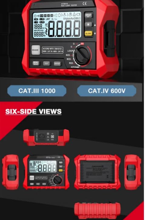
Figure 7.1: Detailed technical specifications and physical dimensions of the HT5910.
| Function | Range | Accuracy | Resolution |
|---|---|---|---|
| Tripping time | x1, IΔN300 (slow 500ms) x5, IΔN40ms (slow 150ms) | ±3ms | 0.1ms |
| Tripping Current | (0.2-1.1)IΔN | ±(0.1IΔN) | 0.01-0.1IΔN |
| Contact Voltage | 0-99.9V | ±(0.2%+0.2V) | 1V |
| ACV (UL-N, UL-L, UL-E) | 0-440V | ±(3%+3V) | 1V |
| Frequency | AC, 45-65Hz | ±(1%+2)Hz | 1Hz |
| Loop resistance (RL) | 0.1-2000Ω | ±(10%+0.2) | 0.1Ω |
| RL Test Current | 0.5 IΔN | ±(10%+10) | 0.5IΔN |
| Test current ratio | x0.5, x1, x5 | ||
| Current Level (IΔN) | 10mA, 30mA, 100mA, 300mA, 500mA | ||
| Trigger Phase Angle | 0° or 180° | ||
| Auto power off | √ | ||
| Backlight | √ | ||
| USB | √ | ||
| Low battery indication | √ | ||
| Data memory | 1000 sets | ||
| Power | 8x1.5V AA batteries (not included) | ||
| Weight | Approx. 708g | ||
| Size | 188x145x73mm | ||
| Safety Rating | EN61010-1, EN61557-3, EN61326-1, CAT IV 600V, CAT III 1000V |
8. Maintenance
- Cleaning: Wipe the instrument with a dry, soft cloth. Do not use abrasive cleaners or solvents.
- Battery Replacement: Replace batteries promptly when the low battery indicator appears to ensure accurate measurements. Refer to Section 5.1 for installation instructions.
- Storage: When not in use for extended periods, remove the batteries and store the instrument in its protective bag in a cool, dry place, away from direct sunlight and extreme temperatures.
- Test Leads: Regularly inspect test leads for any signs of damage, such as cuts, cracks, or frayed insulation. Replace damaged leads immediately.
9. Troubleshooting
| Problem | Possible Cause | Solution |
|---|---|---|
| Instrument does not power on. | Dead or incorrectly installed batteries. | Check battery polarity and replace with new 8x1.5V AA batteries. |
| Low battery indicator displayed. | Batteries are low. | Replace all 8x1.5V AA batteries. |
| Display shows ">>440V" or warning symbol. | Input voltage exceeds safe limits. | Immediately disconnect the instrument from the circuit. Verify the circuit voltage is within the instrument's specified range (0-440V ACV). |
| Inaccurate or no readings. | Loose test lead connections, incorrect mode selection, or damaged leads. | Ensure test leads are securely connected. Verify the correct measurement mode is selected. Inspect test leads for damage and replace if necessary. |
| Instrument automatically shuts off. | Auto power off feature activated due to inactivity. | Rotate the function knob to OFF, wait 5 seconds, then select the desired mode to resume operation. |
10. Warranty and Support
For warranty information and technical support, please refer to the warranty card included with your product or contact VIHELM customer service through the retailer where the product was purchased. Keep your purchase receipt as proof of purchase.