
iGaging 35-600-P6
iGaging EZ-View Digital Planer Readout DRO User Manual
Brand: iGaging | Model: 35-600-P6
Introduction
The iGaging EZ-View Digital Planer Readout (DRO) is designed to enhance the precision and repeatability of your portable planer. This device eliminates guesswork, allowing you to accurately set and repeat exact thickness settings for various wood types. It supports measurements in decimal inches, fractions, and millimeters, and offers both absolute and incremental measuring modes. The unit features an X-LARGE and easy-to-read LCD display and boasts an IP54 dust and moisture protective rating.
Product Overview

The iGaging EZ-View Digital Planer Readout (DRO) installed on a portable planer, showing the digital display and measuring scale.

A close-up view of the EZ-View DRO's large LCD display, showing measurement in inches and control buttons for SET, CAL/0, and MODE.
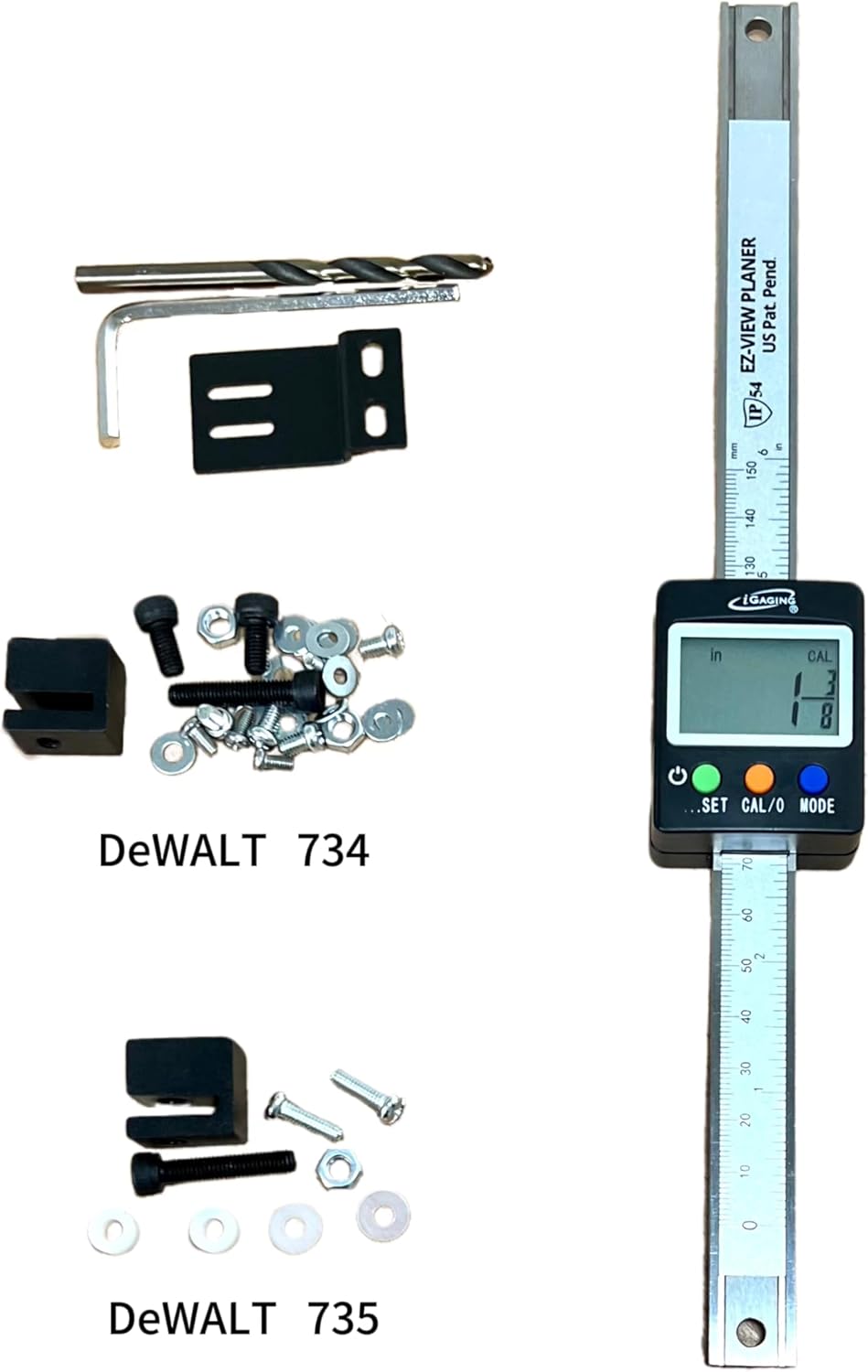
The complete kit includes the digital readout unit, measuring scale, mounting brackets, various screws, nuts, washers, a drill bit, and an M4 hex key, separated for Dewalt 734 and Dewalt 735 compatibility.
Setup & Installation
The EZ-View Digital Planer Readout kit includes all necessary brackets, parts, and tooling for easy mounting on many portable planer models, including Dewalt 734 and 735.
Installation for Dewalt 734

Detailed instructions and diagrams for installing the EZ-View DRO on a Dewalt 734 planer.
- Install the Display Mounting Brackets onto the back of the display using 2 sets of the Display Back Mounting Screws & Washers sets.
- Replace the scale reading indicator from the Dewalt 734 with the Display Mounting Bracket. Use only two sets of the Bracket Mounting Screws and Washers. Do not tighten the screws at this stage.
- Align the Readout Beam from top to bottom, ensuring it is vertically straight and fits perfectly. Use a meter to mark the position of the Beam Top Hole, then use the provided drill bit to drill a hole.
- Assemble the Beam to the machine frame using the Beam Top Spacer and Screw.
- Once everything is fitted correctly, tighten all the screws. Test the fitting and movement by moving the planer up and down. Observe and stop the machine's movement if the fitting is off. Adjust the position of the Display Mounting Bracket using the Display Back Mounting Screws if needed.
Installation for Dewalt 735

Detailed instructions and diagrams for installing the EZ-View DRO on a Dewalt 735 planer.
Based on the installation guide for Dewalt 734, this product can be adapted to fit on Dewalt 735 Planer with the following steps:
- Assemble the U Block Spacer using the M5x20mm screw to the Auxiliary hole at the lower end of the DRO display. Place the DRO in the front of the Planer ruler. Find an ideal location in the center and/or ruler bracket to drill a hole using the supplied M5 drill. Before drilling, please test the overall fit between the DRO and the planer. Make sure the hole location is suitable to have enough space for the DRO display unit to drop to the lowest usable height of the planer.
- Use supplied M5x20mm screw + U Block + M5 nut to secure the DRO beam to the ruler bracket.
- Remove the reference guide and the two screws from the planer.
- Use the supplied two M4x20mm screws + M4x5mm Bushings to mount the display mounting bracket to the machine to finish the installation.
Operating Instructions
The EZ-View DRO offers intuitive controls for precise measurement.
Power and Preset (SET Button)
- Turn On/Off: Long press the SET key (3 seconds) to turn the unit on or off.
- Preset Value: Long press the SET key (3 seconds) to preset a preferred number value. "CAL" will blink on the display. Long press the key again, the first number digit will blink. Short press the same key to change the number value. Long press the key to move to the next digit. Repeat until the last digit is set. Long press the key again, "CAL" will blink. Short press the key to save and exit the mode. "CAL" will stop blinking. Preset value can only be set in inch decimal and metric decimal modes.
Measurement Modes (MODE Button)
- Short press the MODE key to switch among inch decimal, metric decimal, and inch fractional reading.
Calibration and Zero Setting (CAL/0 Button)
- Short press the CAL/0 key to switch between the calibrated measuring and incremental / temporary zero reading.
- Short press the CAL/0 key again, the display will show "INC" to enter an incremental zero setting.
- To return to the calibrated measurement reading, short press the CAL/0 key again to exit. The display will now show "CAL".
Calibration
Calibration of the DRO requires a freshly planed board with the thickness dimension entered on the DRO. The actual measurement is relevant but must be from the board measurement. Follow these steps:
- Run some wood through the planer so that the top & bottom are flat and uniform.
- At this point, DO NOT move the height of the planer.
- Measure that board's thickness with a digital caliper.
- Short press the green power button to turn the DRO on.
- Use the blue SET button to switch the display to decimal inch (0.000).
- Short press the green button until the first digit on the left is blinking (it takes several seconds).
- Short press the green button repeatedly to increment the first digit until it reads the caliper measurement.
- Skip and go to the next step if zero.
- Long press the green button until the next digit is blinking.
- Repeat steps 6 & 7 until all numbers are the same as what's on your caliper.
Troubleshooting
- False Display or Inaccurate Reading: In case of false display or inaccurate reading, it is recommended to replace the battery (CR2032) for a re-start.
- Difficulty Setting Zero in Imperial: If you experience difficulty setting zero in imperial units, try setting the unit in millimeters first using digital calipers, then switch back to imperial. The unit should automatically have the imperial setting.
- Mounting Issues: Ensure all brackets and screws are securely fastened and aligned. Test the planer's movement after installation to confirm smooth operation and proper fit. Adjust mounting bracket position if necessary.
Specifications
| Brand | iGaging |
| Model Number | 35-600-P6 |
| Material | Aluminum, Alloy Steel, Plastic |
| Style | Digital Read Out for planer |
| Item Weight | 15 Ounces |
| Operation Mode | Manual |
| Power Source | Battery Powered (CR2032) |
| Reading / Resolution | 0.0005" inch, 0.01mm, 32nd fractional |
| Accuracy | +/- 0.001" |
| Protection Rating | IP54 (Dust and Moisture Protective) |
| Display | X-LARGE and Easy to Read LCD Display |
| Compatibility | Fits most portable planer brands, including Dewalt 734 and 735 |
| Included Components | Gauge, instruction manual, mounting parts, and tooling (drill bit, hex key) |
Maintenance
To ensure the longevity and accuracy of your iGaging EZ-View Digital Planer Readout, follow these general maintenance guidelines:
- Cleaning: Regularly wipe the display and scale with a soft, dry cloth. Avoid using harsh chemicals or abrasive materials that could damage the screen or finish.
- Battery Replacement: The unit is powered by a CR2032 battery. If the display becomes dim or shows inaccurate readings, replace the battery. Ensure the new battery is inserted with the correct polarity.
- Storage: When not in use for extended periods, store the planer with the DRO in a clean, dry environment to protect it from excessive dust and moisture, despite its IP54 rating.
- Check Connections: Periodically inspect all mounting screws and brackets to ensure they remain tight and secure. Loose connections can affect accuracy.
Warranty and Support
iGaging products are designed and shipped from California, USA. For specific warranty information, product support, or to purchase replacement parts, please visit the official iGaging website or contact their customer service directly.
For more information, visit: www.iGAGING.com
Related documents35-600-P6


Ask a question about this manual
Ask about setup, troubleshooting, compatibility, parts, safety, or missing instructions. Manuals+ will review the question and use this page’s manual context to help answer it.