
1. Introduction
This manual provides detailed instructions for the installation, operation, and maintenance of your FORGING MOUNT Lockable RV TV Mount (Model HY9110). This full-motion wall mount is designed for 13-43 inch TVs and monitors, offering secure and flexible viewing options in mobile environments such as RVs, campers, motorhomes, trailers, boats, and trucks. Its unique locking mechanism ensures your display remains stable during transit.
2. Safety Information
WARNING: Failure to read and follow all instructions may result in personal injury, property damage, or voiding of warranty.
- Weight Capacity: Do not exceed the maximum weight capacity of 55 lbs (25 kg). Ensure your TV/monitor's weight is within this limit.
- Screen Size: This mount is compatible with screens from 13 to 43 inches.
- VESA Compatibility: Verify your TV/monitor's VESA pattern (mounting hole spacing) is compatible with 75x75mm, 100x100mm, 100x200mm, 200x100mm, or 200x200mm.
- Wall Type: This mount is designed for installation on single wood studs, solid concrete walls, or brick walls. DO NOT install on drywall alone. Drywall does not provide sufficient support for the mount and TV.
- Professional Installation: If you are unsure about the installation process or the structural integrity of your mounting surface, consult a qualified professional.
- Moving Vehicles: Always engage the locking mechanism before moving your vehicle (RV, camper, boat, etc.) to prevent damage to the TV and mount.
- Children: Keep children away from the mounting area during installation and ensure the TV is securely locked when not in use to prevent accidental injury.
3. Package Contents
Carefully unpack the box and ensure all components are present and undamaged. If any parts are missing or defective, contact FORGING MOUNT customer service.

Image: Overview of the FORGING MOUNT Lockable RV TV Mount components. This includes the main mount assembly with its articulating arm, the TV plate, three cable ties for cable management, and a small bubble level to aid in installation.
Included Hardware:
- Wall Plate Assembly
- TV Plate
- Articulating Arm
- Mounting Hardware (various screws, washers, spacers for TV and wall)
- Cable Ties (x3)
- Bubble Level (x1)
- Instruction Manual
4. Specifications
| Feature | Specification |
|---|---|
| Model Number | HY9110 |
| Compatible TV Sizes | 13 - 43 inches |
| Maximum Load Capacity | 55 lbs (25 kg) |
| VESA Compatibility | 75x75mm, 100x100mm, 100x200mm, 200x100mm, 200x200mm |
| Movement Type | Articulating, Swivel, Tilt, Rotation |
| Tilt Angle | Up 5°, Down 12° |
| Swivel Angle | 180° (left/right) |
| Rotation | +/- 90° (Landscape to Portrait) |
| Extension from Wall | 3.07 inches (retracted) to 19.09 inches (extended) |
| Material | Alloy Steel |
| Product Dimensions | 18.2 x 10.23 x 3.15 inches |
| Item Weight | 4.4 lbs |
| Color | Black |

Image: The mount securely holding a TV on a boat, highlighting its robust construction and 55 lbs weight capacity, suitable for marine and RV environments.
5. Setup and Installation
Before beginning installation, ensure you have all necessary tools (e.g., drill, stud finder, screwdriver, wrench) and have reviewed the safety information.
Step 1: Pre-Installation Checks
- Verify TV Compatibility: Confirm your TV's size (13-43 inches), weight (under 55 lbs), and VESA pattern (75x75mm to 200x200mm) are compatible.
- Check Wall Type: Identify if your mounting surface is a wood stud, solid concrete, or brick. Do not install on drywall alone.
- Cable Clearance: Ensure the TV's cable outlets will not be blocked by the mount's TV plate.
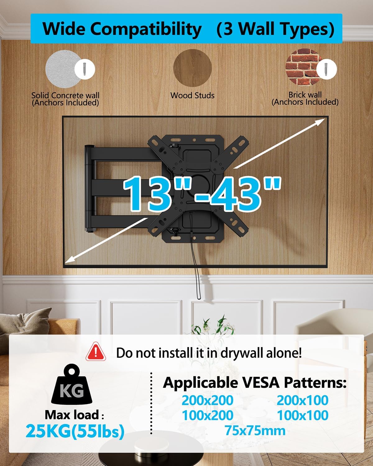
Image: Visual guide for wall compatibility and VESA patterns. It illustrates that the mount supports wood studs, concrete, and brick walls, and specifies VESA sizes from 75x75mm to 200x200mm. A critical warning against installing on drywall only is included.

Image: Detailed illustration of common VESA mounting patterns (75x75mm, 100x100mm, 100x200mm, 200x100mm, 200x200mm) to help users identify their TV's compatibility.
Step 2: Attach TV Plate to TV
- Carefully place your TV face-down on a soft, clean surface to prevent screen damage.
- Align the TV plate with the VESA mounting holes on the back of your TV.
- Select the appropriate screws and spacers from the provided hardware kit that fit your TV's mounting holes.
- Secure the TV plate to the TV using the chosen screws and spacers. Do not overtighten.
Step 3: Install Wall Plate
- Determine the desired mounting location on your wall. Use a stud finder to locate a wood stud if applicable.
- Hold the wall plate against the wall at the desired height and use the included bubble level to ensure it is perfectly horizontal.
- Mark the drilling locations through the holes on the wall plate.
- Drill pilot holes according to the instructions for your specific wall type (wood, concrete, or brick).
- Secure the wall plate to the wall using the appropriate lag bolts and washers. Ensure it is firmly attached.
Step 4: Hang TV on Wall Plate
- With assistance, carefully lift the TV (with the TV plate attached).
- Hook the TV plate onto the wall plate assembly. Ensure it is properly seated and secure.
- Engage the locking mechanism (refer to Section 6.1) to secure the TV to the mount.

Image: A simplified three-step installation guide showing the process of attaching the TV plate to the TV, mounting the wall plate, and finally hanging the TV onto the wall plate.
6. Operating Instructions
6.1 Locking Mechanism
The unique pull-cord locking mechanism secures your TV during travel.
- To Lock: Push the TV firmly against the wall plate until you hear a click, indicating the locking mechanism has engaged. The pull cord should hang freely.
- To Unlock: Gently pull the cord downwards. This will release the lock, allowing you to extend and adjust the TV.
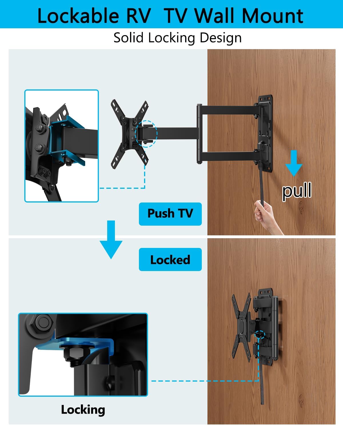
Image: Visual explanation of the locking mechanism. It shows the action of pushing the TV to engage the lock and pulling the cord to disengage it, ensuring the TV is secure or ready for adjustment.
6.2 Adjusting Tilt
The mount allows for a tilt range of 5° up and 12° down to reduce glare and optimize viewing angles.
- Loosen the tilt adjustment knobs or bolts on the TV plate (if applicable, refer to diagram in manual).
- Carefully adjust the TV to your desired vertical angle.
- Tighten the knobs/bolts to secure the tilt position.
6.3 Adjusting Swivel
The articulating arm allows for a 180° swivel (90° left and 90° right) for flexible viewing from various positions.
- Gently push or pull the TV to swivel it left or right along the articulating arm.
- The friction of the arm is designed to hold the position. If it feels too loose or too stiff, refer to the maintenance section for adjustment.
6.4 Landscape to Portrait Rotation
The faceplate can rotate +/- 90° to switch between landscape and portrait orientation.
- Ensure the TV is unlocked and extended slightly from the wall.
- Carefully rotate the TV clockwise or counter-clockwise to achieve the desired orientation.

Image: A TV displayed in an RV interior, rotated 90 degrees to portrait mode, illustrating the mount's capability to switch between landscape and portrait orientations for varied content viewing.
6.5 Extending and Retracting
The full-motion arm allows the TV to extend up to 19.09 inches from the wall and retract to 3.07 inches.
- Gently pull the TV towards you to extend the arm.
- Push the TV back towards the wall to retract the arm. Ensure the locking mechanism is engaged when fully retracted for travel.

Image: Illustration of the mount's full motion range, detailing its 180-degree swivel, 5 to 10-degree tilt, and the ability to extend up to 19.09 inches and retract to 3.07 inches from the wall.
7. Maintenance
- Cleaning: Wipe the mount with a soft, dry cloth. Avoid abrasive cleaners or solvents.
- Periodic Checks: Regularly inspect all screws and bolts to ensure they are tight. Re-tighten if necessary.
- Lubrication: The articulating joints are designed for smooth movement. If movement becomes stiff or noisy, a small amount of silicone-based lubricant can be applied to the pivot points.
- Locking Mechanism: Ensure the pull cord and locking mechanism operate freely. Keep the area clear of obstructions.
8. Troubleshooting
Issue: TV is not level after installation.
Solution: Check the wall plate installation using the bubble level. If the wall plate is level, there may be a slight adjustment available on the TV plate. Consult the detailed manual for specific leveling adjustments.
Issue: Mount feels loose or unstable.
Solution: Immediately remove the TV. Re-check all wall mounting bolts and TV plate screws for tightness. Ensure the wall type is appropriate and the installation followed all instructions. If the issue persists, contact customer support.
Issue: Difficulty engaging or disengaging the locking mechanism.
Solution: Ensure the TV is pushed fully against the wall plate when locking. When unlocking, pull the cord firmly and directly downwards. Check for any obstructions around the locking mechanism.
Issue: Arm movement is too stiff or too loose.
Solution: Some joints may have adjustable tension bolts. Refer to the full instruction manual for diagrams showing these adjustment points. Use the provided tool (if applicable) to adjust the tension to your preference.
9. Warranty and Support
FORGING MOUNT products are manufactured with quality and customer satisfaction in mind. This product comes with a limited warranty against defects in materials and workmanship under normal use. For specific warranty details, claims, or technical support, please refer to the warranty card included with your product or visit the official FORGING MOUNT website.
For direct assistance, please contact FORGING MOUNT customer service through their official channels. When contacting support, please have your model number (HY9110) and purchase information ready.
