
JMT ADT-F36B-F37B-D8S
JMT ADT-F36B-F37B-D8S PCI-e 4.0 X16 to X8 X8 MCIO Bifurcation Adapter Riser Card User Manual
1. Introduction
This user manual provides detailed information and instructions for the JMT ADT-F36B-F37B-D8S PCI-e 4.0 X16 to X8 X8 MCIO Bifurcation Adapter Riser Card. This product is designed to split a single PCIe 4.0 x16 slot into two PCIe 4.0 x8 slots using MCIO cables, enabling flexible expansion for various computing needs, particularly in systems requiring multiple high-bandwidth PCIe devices.
2. Product Overview
The JMT ADT-F36B-F37B-D8S is a high-performance bifurcation adapter designed for advanced computing environments. It facilitates the expansion of PCIe connectivity by converting a single x16 slot into two x8 slots, maintaining PCIe 4.0 speeds.
2.1 Components
- ADT-F36B Main Board: The primary board that plugs into the motherboard's PCIe x16 slot.
- ADT-F37B Riser Boards (x2): Two individual riser boards, each providing a PCIe x8 slot.
- MCIO Cables (x2): High-speed cables connecting the ADT-F36B main board to the ADT-F37B riser boards.
- SATA Power Adapter Cable: For providing necessary 12V power to the adapter.
2.2 Key Features
- Speed Bandwidth: PCIe 4.0 x16, providing 256G/bps, backward compatible with Gen3 and Gen2.
- Bifurcation Support: Designed for motherboards that support PCIe bifurcation (x16 to x8/x8).
- High-Quality Construction: Features UL certified wire (5th generation FFC flat cable with full coverage shield, 1.0mm thickness), UL certified PCB board with 10µ" gold-plated gold fingers for excellent conductivity, and PA10T/LCP connector shells with 15µ" gold-plated terminals.
- Flexible Design: Supports various configurations including one-to-one and one-to-two splitting.
- Power Requirement: Requires connection of the included SATA power adapter cable to a 12V power supply.
2.3 Product Visuals
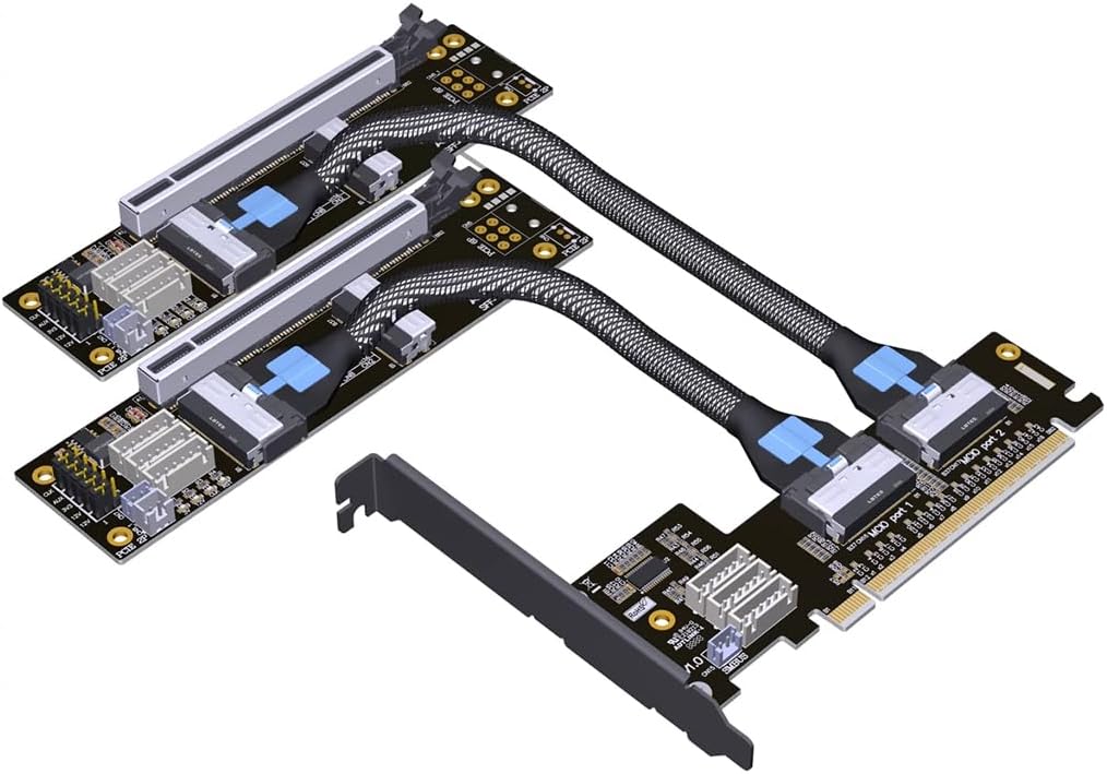
Figure 1: Overview of the JMT ADT-F36B-F37B-D8S PCIe Bifurcation Adapter, showing the main board, two riser boards, and the connecting MCIO cables.

Figure 2: Detailed view of one ADT-F37B riser board, highlighting the PCIe x8 slot and power connectors.

Figure 3: The MCIO-x8 cables used for connecting the main board to the riser boards, featuring a durable braided design.
3. Setup and Installation
Proper installation is crucial for the functionality and stability of the bifurcation adapter. Please follow these steps carefully.
3.1 Pre-installation Checklist
- Ensure your motherboard supports PCIe Bifurcation (x16 to x8/x8 splitting). This is a critical requirement. Refer to your motherboard's manual or BIOS settings.
- Power off your computer and disconnect it from the power source.
- Open your computer case and locate an available PCIe x16 slot.
- Have the necessary tools ready (e.g., screwdriver).
3.2 Installation Steps
- Install the ADT-F36B Main Board: Carefully insert the ADT-F36B main board into an available PCIe x16 slot on your motherboard. Ensure it is seated firmly.
- Connect SATA Power: Connect the provided SATA power adapter cable to the white 12V power input on the ADT-F36B main board. Connect the other end to a SATA power connector from your power supply. This 12V power supply is essential for stable operation.
- Connect MCIO Cables: Connect one end of each MCIO cable to the corresponding ports on the ADT-F36B main board.
- Install ADT-F37B Riser Boards: Install the two ADT-F37B riser boards into your desired locations within the chassis. These can be mounted using a BK7 bracket (if available) for added stability.
- Connect MCIO Cables to Riser Boards: Connect the other end of each MCIO cable to the respective ADT-F37B riser board. Ensure a secure connection.
- Install PCIe Devices: Insert your PCIe x8 devices (e.g., GPUs, NVMe expansion cards) into the PCIe x8 slots on the ADT-F37B riser boards.
- Secure Components: Ensure all boards and cables are securely fastened and do not obstruct airflow.
- Close Case and Power On: Close your computer case, reconnect the power, and power on your system.
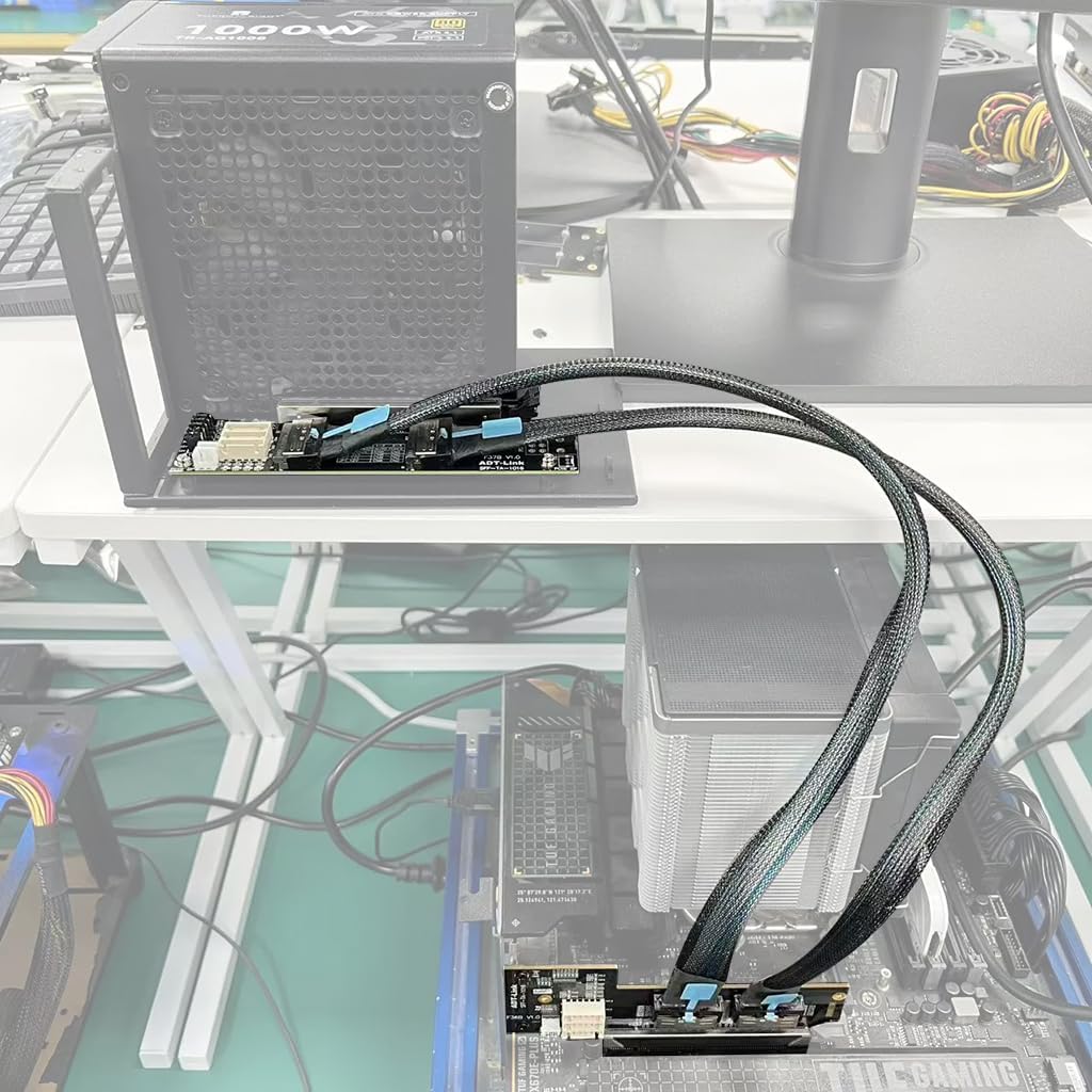
Figure 4: An example setup showing the JMT bifurcation adapter connected to a motherboard and extending to external PCIe devices.
3.3 BIOS Configuration
After physical installation, you may need to enter your motherboard's BIOS/UEFI settings to enable PCIe bifurcation for the slot where the ADT-F36B is installed. Look for settings related to
Ask a question about this manual
Ask about setup, troubleshooting, compatibility, parts, safety, or missing instructions. Manuals+ will review the question and use this page’s manual context to help answer it.