1. Introduction
This manual provides essential instructions for the installation, operation, and maintenance of your Gpxhbcb Electric Bike Conversion Kit. Please read this manual thoroughly before attempting installation or use to ensure safe and efficient operation.
The Gpxhbcb Electric Bike Conversion Kit allows you to transform a standard bicycle into an electric bicycle, providing pedal assistance and motor power for an enhanced riding experience. This specific kit is designed for bicycles with a 700C wheel size and features a 48V 1000W brushless front hub motor.

Figure 1.1: Overview of the Gpxhbcb Electric Bike Conversion Kit components, including the front hub motor wheel, controller, display, throttle, brake levers, and pedal assist sensor.
2. Package Contents
Before beginning installation, verify that all components listed below are present in your package. If any items are missing or damaged, please contact customer service.
- Motor Front Flange (Hub Motor Wheel) x1
- 15A Controller x1
- Monitor (LCD Display) x1
- Throttle x1
- 115PDD Electronic Brake Levers x1 pair
- PAS Sensor x1
- MA-BK-2R Brake Sensor x1
- Disc Brake (if included with your specific kit)
- Controller Bag (Gift) x1
- Wire Protection Film (Gift) x1 set
Note: Lithium battery is not included. The power and voltage of the battery you purchase must match the kit's settings (48V).

Figure 2.1: Visual representation of the components included in the Gpxhbcb Electric Bike Conversion Kit package.
3. Setup and Installation
Converting your bicycle to an e-bike with this kit typically takes 1-2 hours. If you are unsure about any step, it is recommended to seek assistance from a professional bike shop.
3.1 Pre-Installation Checks
- Ensure your bicycle's front fork opening size is 100mm to accommodate the front hub motor.
- Verify that the wheel size of your bicycle matches the kit (700C).
- Prepare necessary tools, including wrenches, screwdrivers, and tire levers.

Figure 3.1: Diagram illustrating the front motor dimensions and the required 100mm front fork opening size for installation.

Figure 3.2: Guide for determining appropriate wheel size and tire compatibility for the conversion kit.
3.2 Component Placement Overview
The following diagram illustrates the general placement of the conversion kit components on a bicycle frame.

Figure 3.3: Schematic diagram showing the typical installation locations for the hub motor, controller, battery management system, smart meter display, and booster (PAS sensor) on a bicycle.
3.3 Installation Steps
- Install the Front Hub Motor Wheel: Remove your original front wheel. Transfer your original tire and inner tube to the new hub motor wheel. Install the hub motor wheel into the front fork.
- Motor Installation Method:
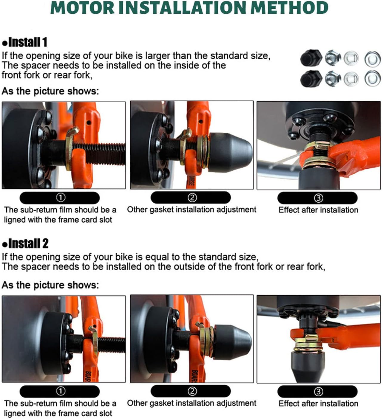
Figure 3.4: Detailed steps for installing the motor, including spacer placement based on fork size. If your bike's opening size is larger than standard, install spacers on the inside. If it's standard, install spacers on the outside. Ensure the sub-return film aligns with the frame card slot.
- Install Controller: Mount the controller in a secure location, typically within the provided controller bag, and connect it according to the wiring diagram.
- Install Display: Attach the LCD display to your handlebars in a position that is easily visible and accessible.
- Install Throttle: Mount the throttle on the handlebars.
- Install Brake Levers: Replace your existing brake levers with the electronic brake levers provided.
- Install PAS Sensor: Install the Pedal Assist System (PAS) sensor on the crank arm near the bottom bracket. The installation distance of the pedal assist device should be approximately 5mm.
- Wiring Connections: Carefully connect all components to the controller. Ensure all connections are firm and that the inner core of each plug is not damaged, broken, or bent. The wiring between the controller and motor ends must be securely connected.
- Battery Connection: Connect your 48V lithium battery (not included) to the controller. Ensure the battery's specifications match the kit's requirements.
4. Operating Instructions
Once installed, your electric bike conversion kit offers several features to enhance your ride.
4.1 LCD Display Functions
The LCD display provides crucial information about your e-bike's status:
- Battery Percentage: Indicates the remaining battery charge.
- Speed: Displays current riding speed.
- Total One-Way Distance: Tracks the distance covered in a single trip.
- Wattage: Shows the motor's power output.
- PAS Level: Indicates the current level of pedal assistance.
- Error Codes: Displays codes for easier troubleshooting if an issue arises.
4.2 Pedal Assist System (PAS)
The PAS sensor allows you to ride without constant throttle engagement. As you pedal, the system detects your pedaling motion and provides motor assistance, making your ride easier and more efficient. You can adjust the level of assistance via the LCD display.
4.3 Throttle Operation
The throttle provides on-demand power, allowing you to accelerate or maintain speed without pedaling. Use the throttle judiciously, especially when starting or in crowded areas.
4.4 Electronic Brake Levers
The electronic brake levers cut off motor power when engaged, ensuring safe braking. Effective braking force is produced once the brakes are applied.
5. Maintenance
Regular maintenance is crucial for the longevity and safe operation of your electric bike conversion kit. While specific maintenance schedules are not provided, general e-bike maintenance practices should be followed:
- Regular Cleaning: Keep the motor, controller, and connections clean and free from dirt and debris.
- Check Connections: Periodically inspect all electrical connections for tightness and signs of wear or corrosion.
- Tire Pressure: Maintain correct tire pressure for optimal performance and safety.
- Brake Inspection: Regularly check brake pads and cables for wear and proper function.
- Battery Care: Follow the manufacturer's instructions for your specific lithium battery regarding charging, storage, and discharge cycles.
- Professional Inspection: Consider periodic inspections by a qualified bicycle mechanic, especially for complex electrical components.
6. Troubleshooting
If you encounter issues with your conversion kit, refer to the following common troubleshooting tips:
- Kit Not Working:
- Ensure all connections between the motor and controller are firm.
- Check that the inner core of each plug is not damaged, broken, or bent.
- Verify that the wiring between the controller and motor ends is securely connected.
- Confirm your battery is charged and properly connected, and its voltage matches the kit's requirements (48V).
- PAS Not Engaging:
- Check the installation distance of the pedal assist device; it should be approximately 5mm.
- Ensure the PAS sensor is correctly aligned and free from obstructions.
- Error Codes on Display: Refer to the LCD display's error codes for specific diagnostic information. Consult the display's separate manual if available, or contact customer support with the error code.
If troubleshooting steps do not resolve the issue, contact Gpxhbcb customer service for further assistance or consult a professional bike technician.
7. Specifications
7.1 General Product Specifications
| Brand | Gpxhbcb |
| Model | Electric Bike Conversion Kit 48V 1000W |
| Wheel Size | 700C |
| Item Weight | 17.6 pounds (approx. 8 kg) |
| Package Dimensions | 20.47 x 20.47 x 9.84 inches |
7.2 Motor Wheel Specifications

Figure 7.1: Detailed specifications for the hub motor wheel, including power, voltage, speed, and construction.
| Rated Power | 1000W | Rated Voltage | 48V |
| Rated Speed | 35-45 km/h | Wheel Size | P25D (700C) |
| RPM | 325-331 RPM | Brake Type | V/Disc Brake Compatible |
| Torque | 57.5-59 N.M | Construction | Gearless |
| Fork Size | 100mm | Weight | Approx. 6.45 kg |
7.3 Controller Specifications

Figure 7.2: Specifications and wiring details for the KT-30A controller, showing various input/output connections.
| Type | KT-30A | Rated Voltage | DC36/48V |
| Rated Power | 1000W | Rated Current | 15A |
| Low Voltage Protection | DC30/40 ± 0.5V | Maximum Current | 30 ± 1A |
| Mosfets | 12 | Size | 172*84*42mm (6.77*3.31*1.65 inches) |
| Speed Set | 1-4.2V | Brake Input | Low-Level |
8. Warranty and Support
8.1 Warranty Information
Specific warranty details for the Gpxhbcb Electric Bike Conversion Kit are not provided in this manual. Please refer to your purchase documentation or contact the seller/manufacturer directly for information regarding warranty coverage and terms.
8.2 Customer Support
For technical assistance, troubleshooting, or inquiries regarding your Gpxhbcb Electric Bike Conversion Kit, please contact:
- The seller from whom you purchased the product.
- Gpxhbcb customer service (contact information typically found on the product packaging or manufacturer's website).
If you require professional installation or repair, it is recommended to consult a local bicycle shop specializing in e-bike conversions.


