1. Introduction
This manual provides essential information for the safe and efficient operation of your POWLSOJX 40A MPPT Solar Charge Controller. Please read these instructions thoroughly before installation and use to ensure optimal performance and longevity of your solar power system.
The POWLSOJX MPPT Solar Charge Controller is designed to maximize power harvest from your solar panels and efficiently charge your battery bank. It features advanced Maximum Power Point Tracking (MPPT) technology, automatic voltage detection, and comprehensive protection functions for various battery types.
2. Safety Precautions
Failure to follow these safety instructions may result in personal injury, damage to the controller, or other equipment.
- Ensure all connections are correct and secure before applying power.
- Always connect the battery first, then the load, and finally the solar panel. Disconnect in the reverse order.
- Install the controller in a well-ventilated area, away from flammable materials and direct sunlight.
- Use appropriate circuit breakers or fuses for all connections (battery, solar panel, load).
- Do not attempt to repair or modify the controller. Refer to qualified personnel for service.
- Wear appropriate personal protective equipment (PPE) such as gloves and eye protection during installation.
- Verify battery voltage and type settings are correct to prevent overcharging or undercharging.
3. Product Overview
The POWLSOJX 40A MPPT Solar Charge Controller is equipped with a clear LCD display, USB charging ports, and robust terminals for reliable connections. Its transparent housing allows for visual inspection of internal components.
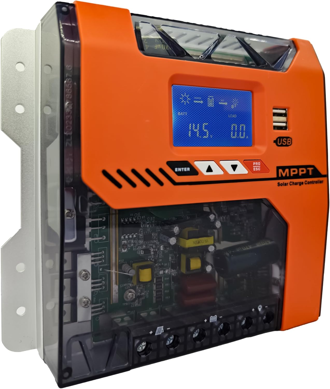
Image: Front view of the POWLSOJX 40A MPPT Solar Charge Controller, showing the LCD screen, control buttons, USB ports, and terminal block.
Key Features:
- High MPPT Conversion Efficiency: Achieves up to 97% energy conversion with DSP chip precision, optimizing power harvest even in low-light conditions.
- 3-Stage Smart Charging: Bulk, Absorption, and Float charging stages extend battery lifespan for lead-acid, GEL, and lithium batteries.
- Automatic Voltage Detection: Automatically recognizes 12V, 24V, 36V, or 48V battery bank voltages.
- Comprehensive Protection: Includes overcharge cutoff, PV reverse polarity auto-shutdown, thermal throttling, current limiting, PV over current, PV short circuit, battery over discharge, load over current, load short circuit, battery over voltage, and over temperature protection.
- User-Friendly Interface: LCD display and intuitive buttons for easy parameter customization and discharge scheduling.
- Industrial-Grade Durability: Aluminum alloy housing with IP32 waterproof rating, designed to withstand dust, humidity, and voltage spikes.
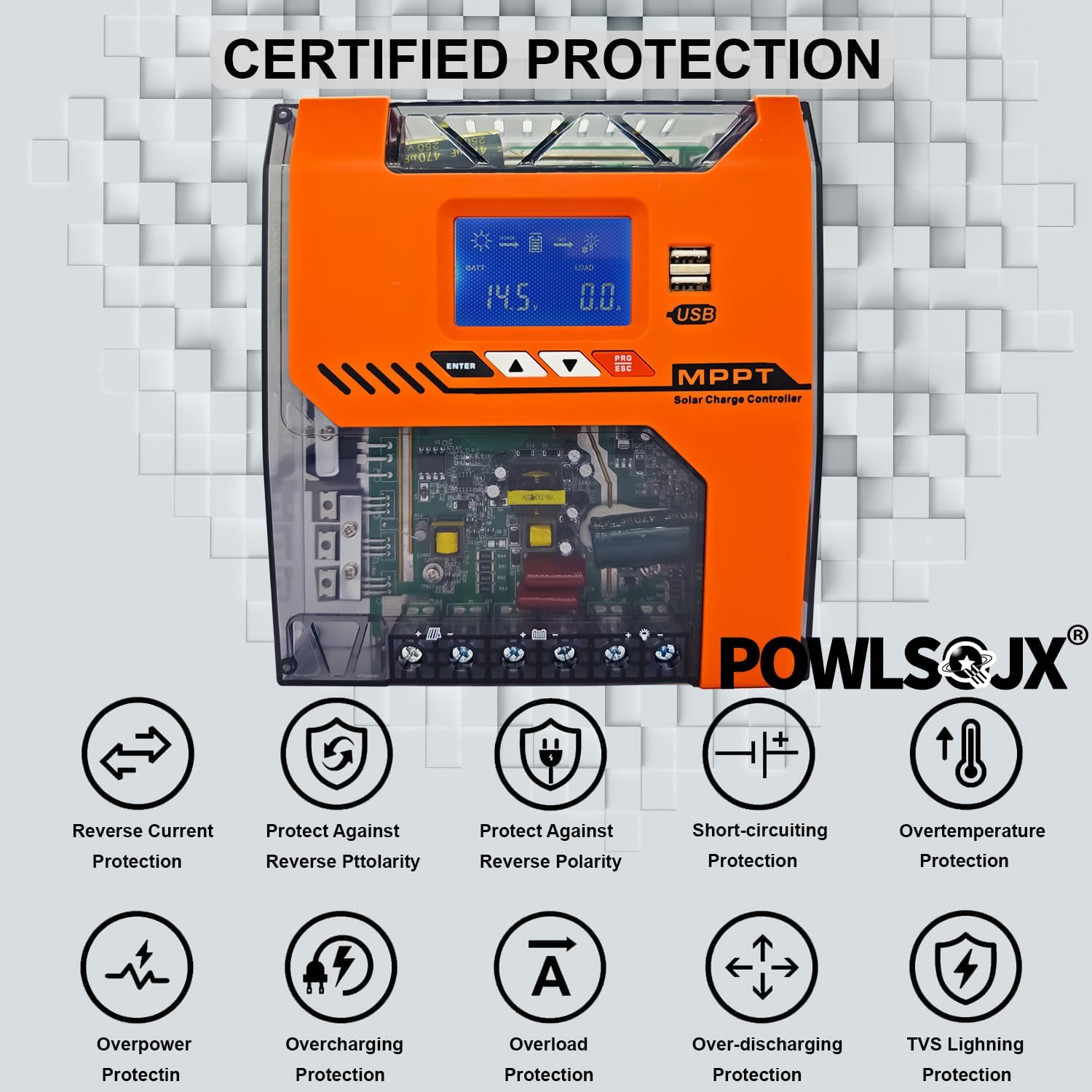
Image: Diagram illustrating various certified protection features of the controller, including reverse current, reverse polarity, short-circuiting, overtemperature, overpower, overcharging, overload, over-discharging, and TVS lightning protection.
4. Installation Guide
Proper installation is crucial for the safe and efficient operation of your solar charge controller. Follow the steps below carefully.
4.1 Mounting Location
- Mount the controller vertically on a non-flammable surface.
- Ensure adequate airflow around the controller for heat dissipation.
- Avoid direct sunlight, high temperatures, and moisture.
4.2 Connection Steps (Critical Order)
Always connect in the following order to prevent damage to the controller or battery:
- Connect the Battery: Connect the battery to the controller's battery terminals. Ensure correct polarity (positive to positive, negative to negative). The controller will automatically detect the battery voltage.
- Connect the DC Load: Connect your DC loads (e.g., lights, pumps) to the controller's load terminals. Ensure correct polarity.
- Connect the Solar Panel: Connect the solar panel(s) to the controller's PV terminals. Ensure correct polarity.
To disconnect, follow the reverse order: Solar Panel → DC Load → Battery.

Image: Detailed wiring diagram showing the correct connection order for the battery, DC load, and PV panel to the solar charge controller, including an optional inverter and fuse.
4.3 Supported Battery Types and PV Input Ranges
The controller supports various battery types and automatically detects system voltage. Ensure your PV input voltage falls within the recommended range for your battery system.
- Supported Battery Types: Lead-acid, GEL, Lithium (LiFePO4, Li-ion), and User-defined.
- PV Input Voltage Ranges:
- When battery 12V: Suggested input solar voltage range DC20V-DC80V; Solar power 240W
- When battery 24V: Suggested input solar voltage range DC37V-DC105V; Solar power 480W
- When battery 36V: Suggested input solar voltage range DC60V-DC150V; Solar power 720W
- When battery 48V: Suggested input solar voltage range DC80V-DC160V; Solar power 960W

Image: Chart detailing recommended PV input voltage and maximum solar power for 12V, 24V, 36V, and 48V battery systems.
5. Operating Instructions
The controller features an LCD display and four buttons for navigation and parameter settings: ENTER, UP, DOWN, and PRG/ESC.
5.1 LCD Display
The LCD displays real-time system status, including battery voltage, charging current, load status, and error indicators.
5.2 Parameter Settings
- Use the UP and DOWN buttons to navigate through menu options.
- Press ENTER to select an option or confirm a setting.
- Press PRG/ESC to exit a menu or cancel an action.
- Saving Settings: After adjusting parameters, ensure you press the designated save button (often the leftmost black button, as per FAQ) to store the changes. Failure to save will result in lost settings.
5.3 Charging Modes
The controller utilizes a 3-stage charging algorithm to optimize battery health:

Image: Graph illustrating the 4-stage MPPT charging process: Bulk Charge, Constant Charging (Absorption), Float Charge, and Equalize Boost/Float Recharge, designed to prolong battery lifespan.
- Bulk Charge: Charges the battery at its maximum current until voltage rises to the absorption level.
- Absorption Charge: Maintains a constant voltage, gradually reducing current as the battery approaches full charge.
- Float Charge: Reduces voltage to a lower level to maintain the battery at full charge, compensating for self-discharge.
- Equalization (for compatible batteries): Periodically overcharges the battery to balance cell voltages and prevent sulfation.
5.4 Discharge Scheduling
The controller allows programming of load runtime for connected DC devices. Refer to the on-screen menu for specific settings to manage your load output.
6. Maintenance
Regular maintenance ensures the longevity and optimal performance of your solar charge controller.
- Cleaning: Periodically clean the controller's exterior with a dry cloth to remove dust and debris. Ensure ventilation openings are clear.
- Connection Check: Annually inspect all wiring connections for tightness and corrosion. Loose connections can cause overheating and power loss.
- Environmental Check: Ensure the installation environment remains within specified temperature and humidity ranges.
- Firmware Updates: Check the manufacturer's website for any available firmware updates.
7. Troubleshooting
This section addresses common issues you might encounter. For problems not listed here, contact customer support.
7.1 Common Issues and Solutions
- Controller Not Powering On:
- Check battery connections and ensure correct polarity.
- Verify battery voltage is above the minimum operating voltage.
- Inspect battery fuses or circuit breakers.
- No Solar Charging:
- Check solar panel connections and polarity.
- Ensure solar panels are receiving adequate sunlight.
- Verify PV input voltage is within the controller's operating range.
- Check PV fuses or circuit breakers.
- Load Not Working:
- Check load connections and polarity.
- Verify load settings and ensure the load output is enabled.
- Check for overcurrent or short-circuit protection activation.
- Settings Not Saving:
- After adjusting parameters, ensure you press the designated save button (e.g., the leftmost black button) to confirm and store the changes.
- Over-voltage Charging / Incorrect Voltage Output:
- Verify the battery type and voltage settings in the controller's menu match your actual battery bank. Incorrect settings can lead to improper charging voltages.
- Ensure the controller's auto-detection is functioning correctly. If issues persist, manually set the battery voltage if the option is available.
- If the controller consistently outputs incorrect voltages despite correct settings, discontinue use and contact customer support.
- Overheating / Burning Smell:
- Immediately disconnect all power sources (solar, battery, load).
- Check for proper ventilation around the controller.
- Inspect wiring for loose connections or short circuits.
- If a burning smell or visible smoke/flames occur, the unit is likely damaged. Do not attempt to re-power. Contact customer support immediately.
7.2 Error Diagnostics
The LCD display or LED indicators may show error codes or warnings. Refer to the specific error code meanings in the full product manual (if available) or contact support with the displayed code.
8. Specifications
| Parameter | Value |
|---|---|
| Model | TN (40A variant) |
| System Voltage | 12V/24V/36V/48V Auto |
| Rated Charge Current | 40A |
| Max. PV Input Voltage | 150V |
| MPPT Efficiency | Up to 97% |
| Display Type | LCD |
| Operating Temperature | -25℃ to +55℃ |
| IP Rating | IP32 |
| Dimensions (L x W x H) | 9.26" x 2.76" x 7.49" |
| Item Weight | 2.5 pounds |
| Material | Metal, Plastic |
9. Warranty Information
Please refer to the product packaging or the official POWLSOJX website for specific warranty terms and conditions. Typically, products are covered against manufacturing defects for a defined period from the date of purchase.
10. Customer Support
For technical assistance, troubleshooting, or warranty claims, please contact POWLSOJX customer support through their official website or the retailer where the product was purchased. Have your model number (TN) and purchase details ready.


