
DEWIN QCXIRIIQY-98956-01zq
DEWIN 2P 63A 220V Automatic Transfer Switch (ATS) G2R Instruction Manual
Model: QCXIRIIQY-98956-01zq | Brand: DEWIN
1. Introduction
The DEWIN 2P 63A 220V Automatic Transfer Switch (ATS) G2R is designed to automatically switch between two power sources, typically a main power supply and a backup power supply, to ensure continuous operation of electrical loads. This device provides a reliable solution for managing power transitions in residential and light commercial applications.
This manual provides essential information for the safe and correct installation, operation, and maintenance of your ATS. Please read it thoroughly before use.

Image: The DEWIN 2P 63A 220V Automatic Transfer Switch, highlighting its compact design, millisecond switching speed, compatibility with mains and generators, and 35mm DIN rail installation.
2. Safety Information
WARNING: Electrical installation should only be performed by qualified personnel. Always disconnect power before installation or maintenance.
- This product is NOT suitable for use with photovoltaic systems.
- It cannot be used as a backup power source for inverters, UPS systems, photovoltaic systems, or solar power generators.
- Ensure the input power supply is connected in the correct phase sequence.
- The operating temperature range is between -5°C and +40°C.
- The storage temperature range is between -25°C and +55°C, and can briefly reach +70°C.
- Installation altitude should not exceed 2000 meters.
- At an ambient temperature of +40°C, the temperature decreases with increasing relative humidity. Adequate measures must be taken to prevent condensation due to temperature fluctuations.
- The ATS enclosure has an IP30 protection rating.
- This product can be used in household distribution boxes. When purchasing a distribution box, pay attention to the height and dimensions of the cover.
- The voltage must not be too low and must be within a ±10% range.
- The manual operation lever cannot be operated in automatic mode.

Image: Operational requirements and safety notes for the DEWIN Automatic Transfer Switch, including environmental conditions and usage restrictions.
3. Product Features
- High Performance: Operated by an excitation electromagnet, enabling extremely fast switching speeds (within milliseconds) to effectively resolve power outage issues.
- Indicator Lights: Equipped with power indicators for general power, emergency power, and load, providing clear status at a glance.
- Easy Installation: Modular structure design with input lines on the same side for convenient wiring. Compact size supports 35mm DIN rail installation, suitable for household distribution boxes.
- Arc Extinguishing System: Features an internal arc extinguishing system capable of rapidly cooling and extinguishing electrical arcs.
- Durable Construction: Made from flame-retardant ABS material with silver alloy contacts, ensuring high conductivity, dust resistance, and adaptability to extreme environments.

Image: Key features of the DEWIN Automatic Transfer Switch, including its electromagnetic drive, modular design, and fast switching capability.
4. Installation and Setup
The DEWIN ATS is designed for 35mm DIN rail mounting. Ensure all power sources are disconnected before proceeding with installation.
4.1 Physical Installation
- Mount the ATS securely onto a 35mm DIN rail within your distribution box.
- Ensure adequate space for wiring and ventilation around the device.

Image: Technical view of the DEWIN ATS, illustrating its modular design and DIN rail mounting points.
4.2 Wiring Diagram
Refer to the diagram below for correct wiring connections. It is crucial to connect the input power supply in the correct phase sequence.

Image: Detailed wiring diagram for the DEWIN 2P 63A ATS, indicating connections for main power, backup power, and load output.
- Common N: Neutral wire for the common (main) power supply.
- Common L: Live wire for the common (main) power supply.
- Spare N: Neutral wire for the backup (emergency) power supply.
- Spare L: Live wire for the backup (emergency) power supply.
- Load Output: Connections for the electrical load.
Ensure all connections are tight and secure to prevent loose contacts and potential hazards.
5. Operating Instructions
The DEWIN ATS offers both automatic and manual operation modes.
5.1 Mode Selection
The device features a selector switch (green lever) to choose between "Auto" and "Manual" modes.
- Auto Mode: In this mode, the ATS will automatically detect the presence of the main power supply (Source I) and switch to it. If the main power fails, it will automatically switch to the backup power supply (Source II).
- Manual Mode: In this mode, you can manually switch between Source I and Source II using the green lever. Important: The lever cannot be operated manually when the device is in "Auto" mode.
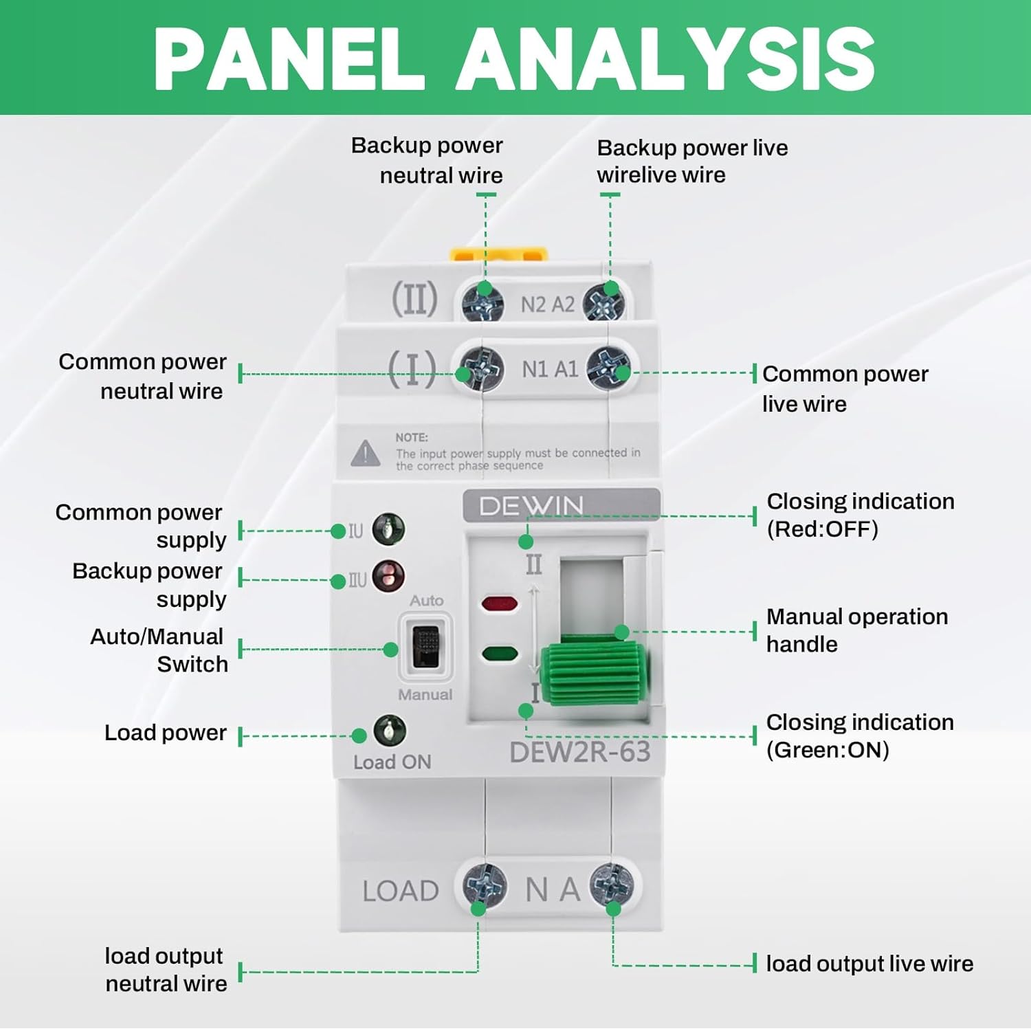
Image: Front panel view of the DEWIN ATS with labels for power inputs, output, mode selector, and indicator lights.
5.2 Indicator Lights
The ATS is equipped with indicator lights to show its operational status:
- Green Light (Load ON): Indicates that power is being supplied to the load.
- Red Light (Closing Indication OFF): Indicates that the corresponding power source is not active or disconnected.
- Green Light (Closing Indication ON): Indicates that the corresponding power source is active and connected.
- If the common or emergency power indicator light flashes, it indicates a malfunction (undervoltage or overvoltage).

Image: Close-up view of the DEWIN ATS showing the status indicator lights (green for ON, red for OFF) and the Auto/Manual switch.
6. Maintenance
Regular maintenance helps ensure the longevity and reliable operation of your DEWIN ATS.
- Periodically inspect all wiring connections to ensure they remain tight and free from corrosion.
- Keep the device clean and free from dust and debris. Use a dry, soft cloth for cleaning.
- Do not use abrasive cleaners or solvents.
- If any damage is observed, disconnect power immediately and contact a qualified technician for repair or replacement.
7. Troubleshooting
If you encounter issues with your DEWIN ATS, refer to the following common troubleshooting steps:
| Problem | Possible Cause | Solution |
|---|---|---|
| Device does not switch automatically. |
|
|
| No power to load. |
|
|
| Indicator lights flashing. |
|
|
For issues not covered here, please contact customer support.
8. Technical Specifications
| Parameter | Value |
|---|---|
| Model | DEW2R-63 2P |
| Material | PC + Copper |
| Rated Operating Current (Le) | 63 A |
| Rated Insulation Voltage (Ui) | 690 V |
| Rated Operating Voltage (Ue) | 220V AC |
| Rated Frequency | 50/60 Hz |
| Number of Poles | 2P |
| Rated Short Circuit Current (Iq) | 50 kA |
| Rated Impact Withstand Voltage | 8 kV |
| Common Circuit | 2 poles 220 V AC (mains network) |
| Auxiliary Circuit | 2 poles 220 V AC (mains network, generator) |
| Contactor Conversion Time | < 50 ms |
| Response Time | < 50 ms |
| Recovery Time | < 50 ms |
| Disconnection Time | < 50 ms |
| Switching Time | < 50 ms |
| Mechanical Durability | 8000 switching cycles |
| Electrical Durability | 1500 switching cycles |
| Application Category | AC-31B |
| Dimensions (LxWxH) | 7.8 x 5 x 10.8 cm |
| Mounting Type | DIN Rail |
| Control Method | Button (Manual), Automatic |
| Compatible Devices | Standard household appliances (up to 63A) |

Image: Comprehensive technical specifications for the DEWIN ATS, detailing electrical parameters and performance metrics.
9. Warranty and Support
For warranty information, please refer to the documentation provided with your purchase or contact the seller directly. DEWIN is committed to providing quality products and customer satisfaction.
10. Customer Support
If you have any questions, require technical assistance, or need to report an issue, please contact DEWIN customer support through the retailer's platform or the official DEWIN website. Please have your product model number (QCXIRIIQY-98956-01zq) and purchase details ready when contacting support.
Ask a question about this manual
Ask about setup, troubleshooting, compatibility, parts, safety, or missing instructions. Manuals+ will review the question and use this page’s manual context to help answer it.