
Introduction
This manual provides detailed instructions for the installation, operation, and maintenance of your Zyyini B150M V3 Computer Motherboard. Please read this manual thoroughly before proceeding with installation to ensure proper setup and to prevent damage to the components. This motherboard is designed for desktop computers, supporting LGA 1151 CPUs and DDR4 memory, offering a stable and efficient platform for various computing needs.
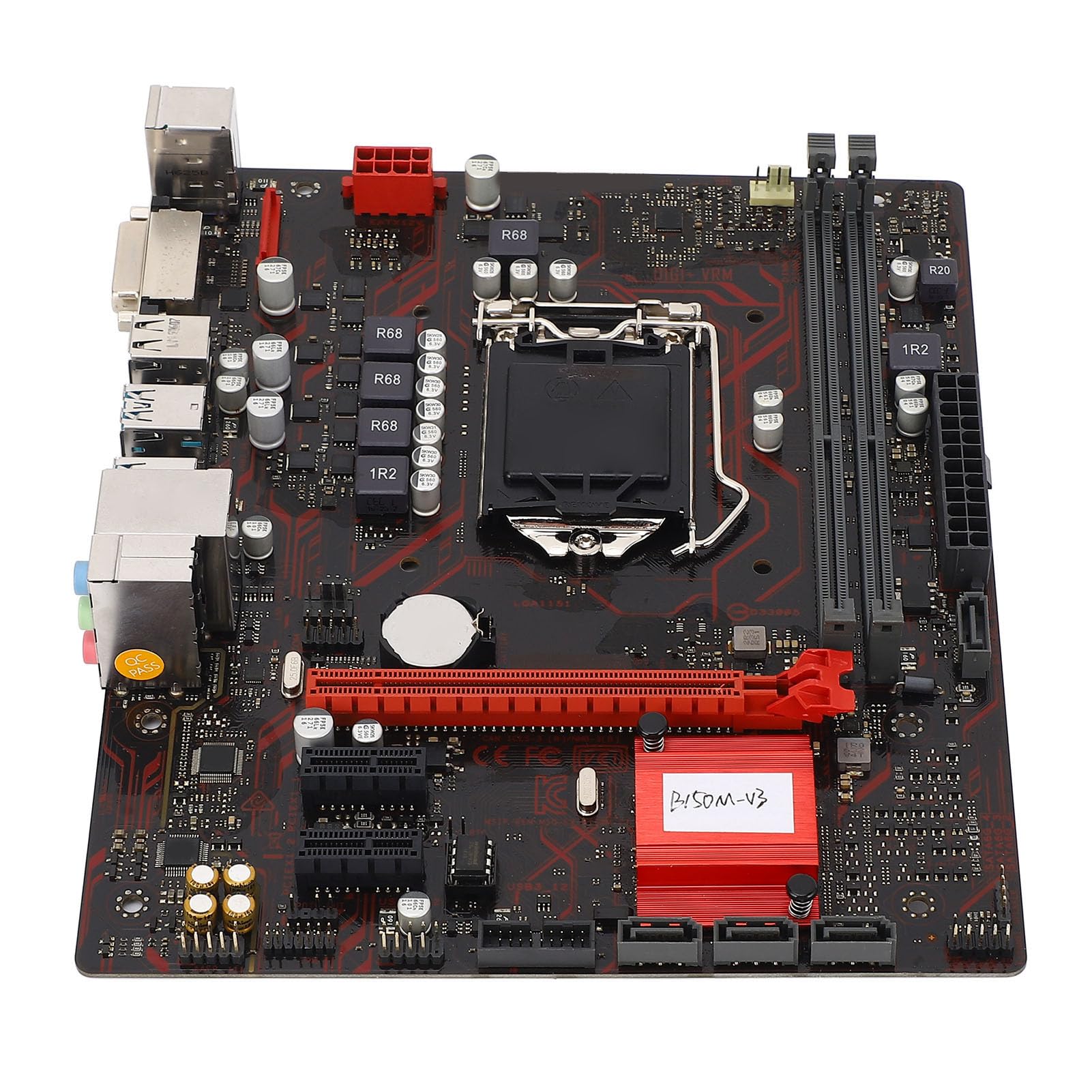
Figure 1: Overview of the Zyyini B150M V3 Motherboard.
Setup and Installation
Before beginning installation, ensure your workspace is clean and static-free. It is recommended to wear an anti-static wrist strap to prevent electrostatic discharge (ESD) damage to components.
1. Safety Precautions
- Always disconnect the power supply from the wall outlet before installing or removing any components.
- Handle components by their edges to avoid touching sensitive circuits.
- Ensure proper grounding to prevent ESD.
- Refer to the CPU, memory, and other component manuals for specific installation instructions.
2. Motherboard Layout

Figure 2: Top-down view highlighting key components and connectors on the motherboard.
Familiarize yourself with the locations of the CPU socket, memory slots, PCI-E slots, SATA ports, and power connectors before installation.
3. CPU Installation (LGA 1151)
- Locate the LGA 1151 CPU socket on the motherboard.
- Gently push down the load lever and pull it sideways to open the CPU socket cover.
- Carefully align the notches on your Intel Core i7/i5/i3/Pentium/Celeron (14nm) processor with the corresponding keys on the socket. Ensure the gold triangle on the CPU matches the triangle on the socket.
- Place the CPU gently into the socket without forcing it.
- Close the load plate and push the load lever back into place until it clicks.

Figure 3: Close-up view of the LGA 1151 CPU socket, ready for processor installation.
4. Memory Installation (DDR4 DIMM)
The motherboard features two DDR4 DIMM slots, supporting dual-channel DDR4 2133MHz memory up to a maximum of 32GB.
- Open the clips at both ends of the DIMM slot.
- Align the notch on the DDR4 memory module with the key in the DIMM slot.
- Insert the memory module firmly into the slot until the clips snap into place. Ensure both clips are closed.

Figure 4: The two DDR4 DIMM slots for memory installation.
5. Storage Device Installation (SATA III & M.2)
The motherboard provides 4 x Serial ATA III interfaces and 1 x M.2 slot for storage devices.
- SATA Devices: Connect one end of a SATA data cable to a SATA III port on the motherboard and the other end to your SATA hard drive or SSD. Connect the SATA power cable from your power supply to the drive.
- M.2 Devices: Insert your M.2 SSD into the M.2 slot, securing it with the provided screw.
6. Expansion Card Installation (PCI-E)
The motherboard includes 1 x PCI-E x16 graphics card slot and 2 x PCI-E x1 slots for expansion cards.
- Align your PCI-E expansion card (e.g., graphics card, sound card, network card) with the desired PCI-E slot.
- Press the card firmly into the slot until it is fully seated. Secure the card with a screw to the chassis.
7. Connecting Peripherals and Front Panel
Connect your USB devices, DVI display, audio devices, and Ethernet cable to the rear I/O panel. Connect the front panel connectors (power button, reset button, USB ports, audio jacks) from your PC case to the corresponding headers on the motherboard.

Figure 5: Detailed view of the rear I/O panel, showing USB, DVI, Ethernet, and audio ports.
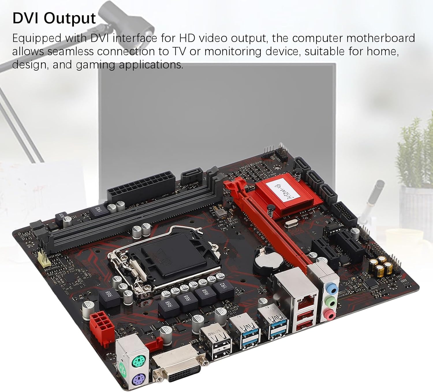
Figure 6: The DVI interface for connecting a display.
8. Power Connections
Connect the 24-pin ATX power connector and the 8-pin CPU power connector from your power supply to the respective ports on the motherboard. Ensure they are firmly seated.

Figure 7: Angled view showing the location of power connectors and other ports.
Operating Instructions
1. Initial Boot-up
After all components are installed and connected, power on your system. The system should initiate the boot process. If no display appears, refer to the troubleshooting section.
2. BIOS/UEFI Configuration
During boot-up, press the designated key (usually DEL or F2) to enter the BIOS/UEFI setup. Here you can configure boot order, system time, and other advanced settings. Save changes before exiting.
3. Driver Installation
After installing your operating system, install the necessary drivers for the motherboard chipset, network, and audio. These are typically provided on a driver CD or available for download from the manufacturer's website.
Maintenance
1. Dust Cleaning
Regularly clean the inside of your computer case to prevent dust buildup, which can lead to overheating and component failure. Use compressed air to gently remove dust from fans, heatsinks, and motherboard surfaces.
2. BIOS Updates
Periodically check the manufacturer's website for BIOS updates. BIOS updates can improve system stability, add support for new hardware, or fix bugs. Follow the update instructions carefully to avoid damaging the motherboard.
Troubleshooting
1. No Power
- Ensure the power supply is connected to the wall outlet and switched on.
- Verify that the 24-pin and 8-pin power connectors are securely attached to the motherboard.
- Check the front panel power switch connection to the motherboard.
2. No Display
- Confirm that the monitor is connected to the correct video output (DVI) on the motherboard or graphics card and is powered on.
- Reseat the memory modules. Try booting with only one memory module installed.
- Reseat the graphics card (if applicable).
- Ensure the CPU is properly installed and the CPU cooler is securely attached.
3. System Instability / Crashes
- Check for overheating. Ensure all fans are working and heatsinks are clean.
- Verify that all components (CPU, RAM, storage) are properly seated.
- Run memory diagnostic tools to check for faulty RAM.
- Ensure all drivers are up to date.
Specifications

Figure 8: The motherboard's robust construction ensures stable performance and longevity.
| Feature | Detail |
|---|---|
| Motherboard Model | B150M-V3 |
| Chipset | B150 Chipset |
| CPU Socket | LGA 1151 |
| Compatible CPU Type | Intel Core i7, i5, i3, Pentium, Celeron (14nm processors) |
| Memory Type | 2 x DDR4 DIMM (Dual Channel) |
| Memory Speed | 2133MHz |
| Maximum Memory Capacity | 32GB |
| PCI-E Standard | PCI-E 3.0 |
| PCI-E x16 Slots | 1 |
| PCI-E x1 Slots | 2 |
| Storage Interfaces | 4 x Serial ATA III, 1 x M.2 |
| USB Interfaces (Rear) | 4 x USB3.0, 4 x USB2.0 |
| USB Interfaces (Internal) | 1 x USB3.0 header, 1 x USB2.0 header |
| Video Interface | 1 x DVI |
| Network Chip | Realtek RTL8111GR Gigabit Ethernet |
| Sound Chip | Realtek ALC887 8-Channel |
| Power Interfaces | One 8-Pin, One 24-Pin |
| Form Factor | M-ATX |
| Power Supply Mode | 5 Phase |
| Other Interfaces | RJ45, Chassis Fan, Internal Speaker, System Panel, Sound, PS/2 Mouse, PS/2 Keyboard, COM |
Warranty Information
For specific warranty terms and conditions, please refer to the documentation provided with your purchase or visit the official Zyyini website. Warranty coverage typically includes defects in materials and workmanship under normal use.
Customer Support
If you encounter any issues that cannot be resolved using this manual, please contact your retailer or visit the Zyyini official support channels for assistance. Have your product model number (B150M-V3) and purchase details ready when seeking support.