1. Introduction
The RadioMaster RP1 V2 is a compact and high-performance 2.4GHz ExpressLRS (ELRS) Nano Receiver designed for remote control applications, particularly in FPV (First Person View) drones and other RC models. This receiver incorporates a Temperature Compensated Crystal Oscillator (TCXO) for enhanced signal stability and accuracy. It features an ESP8285 MCU and SX1280 RF chip, offering low-latency and high-refresh-rate communication. The RP1 V2 supports WiFi for convenient firmware updates and configuration via a web interface.
2. Product Overview
2.1 Key Features
- Integrated TCXO (Temperature Compensated Crystal Oscillator) for reliable and stable signal reception.
- Open-source ExpressLRS based receiver with ESP8285 MCU and SX1280 RF chip.
- Built-in WiFi for convenient firmware upgrades and configuration via WebUI.
- UFL antenna socket for full-range antenna use.
- Optimized PCB design for improved heat dissipation.
- Upgraded rigid antenna for enhanced durability and performance.
- Improved solder pads for easier connection.
- Compatible with all 2.4GHz ExpressLRS modules and transmitters.
2.2 Package Contents
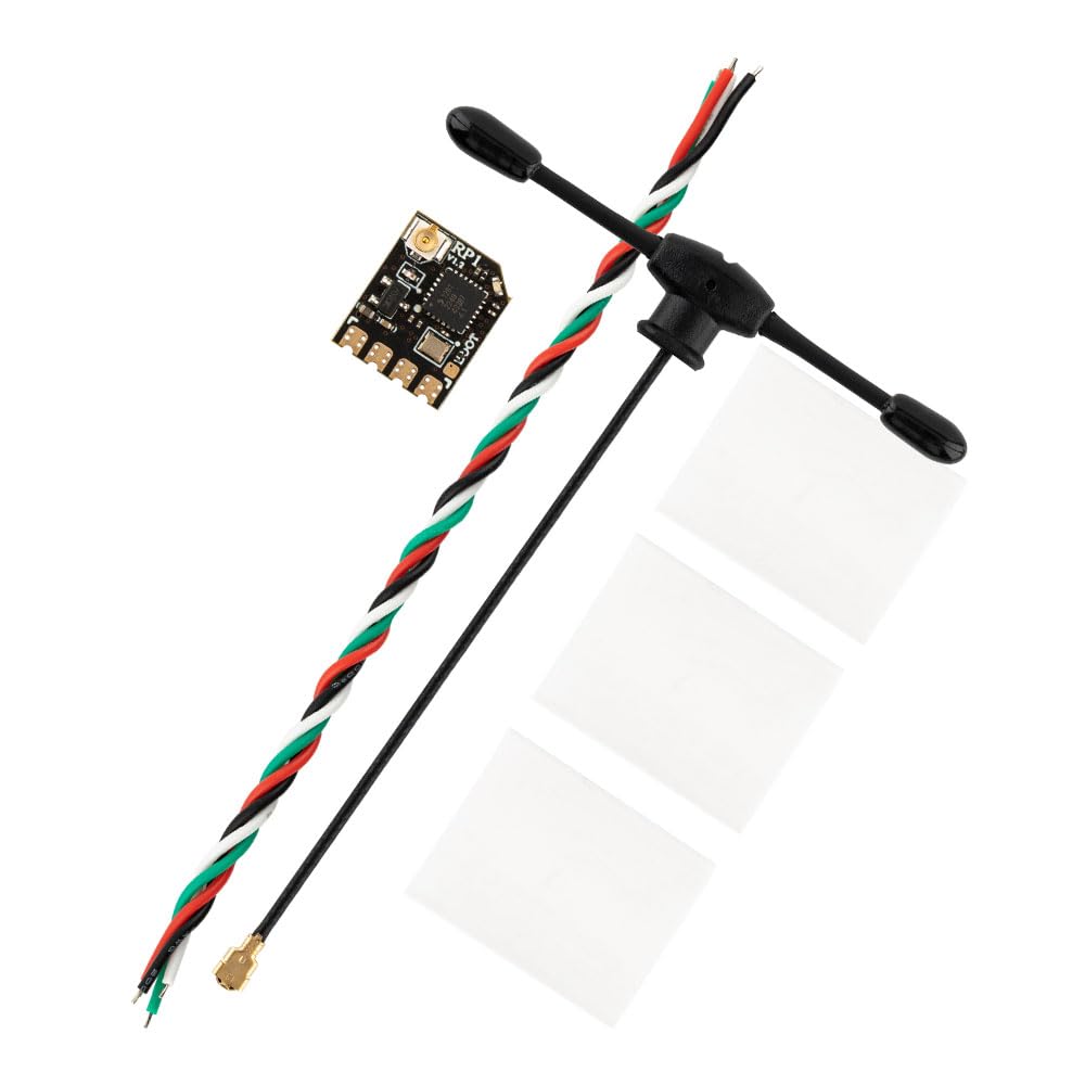
- 1 x RP1 V2 ExpressLRS 2.4GHz Nano Receiver
- 1 x 65mm UFL 2.4GHz T Antenna
- 1 x CRSF wire
- 1 x User Manual (this document)

The image shows the RadioMaster RP1 V2 Nano ExpressLRS Receiver with the included 65mm UFL 2.4GHz T Antenna connected. This antenna is essential for full-range operation.
3. Specifications
| Item | RP1 Nano ExpressLRS 2.4GHz Receiver |
| Type | ISM |
| MCU | ESP8285 |
| RF Chip | SEMTECH SX1281 |
| Telemetry RF Power | 10mW |
| Antenna | 65mm 2.4GHz T Antenna |
| Frequency Range | 2.404 - 2.479 GHz |
| Maximum Receive Refresh Rate | 500Hz / F1000Hz |
| Minimum Receiver Refresh Rate | 25Hz |
| Working Voltage | 5V |
| Weight | 2.2g (Including antenna) |
| Dimension | 13mm x 11mm x 3mm |
| Firmware Version | ExpressLRS v2.4 pre-installed |
| FW Target | RadioMaster RP1/2 2400 RX |
| Bus Interface | CRSF |
This image displays the RadioMaster RP1 V2 Nano ExpressLRS Receiver, highlighting its compact dimensions of 13mm in length, 11mm in width, and 3mm in height. The image shows the UFL antenna connector and solder pads.
4. Setup
4.1 Wiring
Connect the RP1 V2 receiver to your flight controller or other compatible device using the provided CRSF wire or by soldering directly to the pads. Ensure correct polarity and data line connections.
- 5V: Connect to a 5V power source from your flight controller.
- GND: Connect to the ground (negative) terminal of your power source.
- TX (Transmit): Connect to the RX (Receive) pad on your flight controller's UART.
- RX (Receive): Connect to the TX (Transmit) pad on your flight controller's UART.

A detailed view of the RadioMaster RP1 V2 receiver's solder pads, clearly labeled for 5V power input, TX (transmit), RX (receive) data lines, and GND (ground). These pads are used for connecting the receiver to a flight controller.
4.2 Binding Procedure
To establish a connection between your RP1 V2 receiver and your ExpressLRS transmitter module, follow these steps:
- Ensure your ExpressLRS transmitter module is powered on and set to binding mode.
- Power on your RP1 V2 receiver.
- Immediately power off the receiver.
- Repeat steps 2 and 3 two more times. After the third power cycle, the receiver's LED should begin a rapid double flash, indicating it is in binding mode.
- Once the receiver is in binding mode, activate the binding function on your ExpressLRS transmitter.
- A successful bind is indicated by a solid LED on the receiver. If the LED remains flashing, repeat the binding process.
5. Operating Instructions
5.1 Firmware Updates via WiFi
The RP1 V2 receiver features built-in WiFi, allowing for convenient firmware updates and configuration without needing a physical connection to a computer.
- Power on the receiver. If it is not connected to a transmitter, it will automatically enter WiFi hotspot mode after a short period.
- On your computer or mobile phone, search for available WiFi networks and connect to the network named "ExpressLRS RX" (or similar, depending on firmware version). The default password is "expresslrs".
- Open a web browser and navigate to 10.0.0.1. This will open the ExpressLRS WebUI.
- From the WebUI, you can update the receiver's firmware by uploading the appropriate .bin file or configure various settings.
- After updating or configuring, save your changes and reboot the receiver.
5.2 Normal Operation
Once bound and configured, the RP1 V2 receiver will automatically connect to your transmitter upon power-up. The solid LED on the receiver indicates a successful connection. The low-latency and high-refresh-rate capabilities of ExpressLRS ensure precise and responsive control for your RC model.
6. Maintenance
To ensure the longevity and optimal performance of your RadioMaster RP1 V2 receiver, consider the following maintenance guidelines:
- Keep Clean: Regularly inspect the receiver for dust, dirt, or debris. Use a soft, dry brush or compressed air to gently clean the PCB and connectors.
- Protect from Elements: Avoid exposing the receiver to moisture, extreme temperatures, or direct sunlight. Consider using conformal coating or heat shrink for additional protection in harsh environments.
- Inspect Connections: Periodically check all soldered connections and the UFL antenna connector for any signs of damage or looseness. Ensure the antenna is securely attached and positioned correctly.
- Firmware Updates: Keep the receiver's firmware updated to the latest stable version to benefit from performance improvements and bug fixes.
7. Troubleshooting
If you encounter issues with your RP1 V2 receiver, refer to the following common troubleshooting steps:
- Receiver Not Binding:
- Ensure your transmitter module is also running the same ExpressLRS firmware version as the receiver.
- Verify the binding procedure (three power cycles) is performed correctly.
- Check that the transmitter is in binding mode and transmitting.
- Confirm the correct firmware target (RadioMaster RP1/2 2400 RX) was flashed to the receiver.
- No Telemetry/Control:
- Check all wiring connections (5V, GND, TX, RX) for correct polarity and secure soldering.
- Verify the UART settings on your flight controller are configured for CRSF protocol.
- Ensure the antenna is properly connected to the UFL port.
- Short Range/Signal Loss:
- Inspect the antenna for any damage or kinks.
- Ensure the antenna is mounted away from carbon fiber, batteries, or other conductive materials that can block the signal.
- Check the power output settings on your transmitter module.
- Consider environmental factors that might interfere with 2.4GHz signals.
- WiFi Hotspot Not Appearing:
- Ensure the receiver is powered on and not currently connected to a transmitter. It typically enters WiFi mode after a few seconds if no transmitter connection is found.
- Try power cycling the receiver again.
8. Safety Information
Please refer to the instruction manual before use. Always operate RC equipment responsibly and in accordance with local laws and regulations. Ensure all connections are secure and correct before powering on your model. Improper installation or use can lead to damage to the product or other components.
9. Warranty and Support
For warranty information and technical support, please contact your retailer or the manufacturer directly. You can find more information about RadioMaster products on their official store: RadioMaster Amazon Store.


