
1. Introduction
The BUUBO TUF-2000M-TM-1 is a digital ultrasonic flow meter module designed for precise measurement and analysis of liquid flow. This module offers high accuracy, a wide measuring range, and robust communication capabilities, making it suitable for industrial automation, process control, and various flow metering applications. Its compact size and local display enhance its versatility.
Key Features:
- High Accuracy: Linearity better than 0.5%, repeatability better than 0.2%, and accuracy better than ±1%.
- Wide Measuring Range: Compatible with various transducer types, supporting pipe sizes from DN15mm to DN6000mm.
- Far Transmission Distance: Connects the module and secondary meter via RS-485 interface, allowing transmission distances up to 1000m.
- Powerful Functions: Includes a 4-20mA current output (one channel) for flow/heat transmission and two OCT outputs for flow/heat switching.
- Input Capabilities: Features three channels for 4-20mA analog input and two channels for Tri-wire resistance signal input (PT100), suitable for calorimeter applications.
- Communication Protocols: Compatible with MODBUS, METER-BUS, Fuji extended protocol, and general water meter protocols.
2. Package Contents
Upon unpacking, please verify that all components listed below are present and in good condition. If any items are missing or damaged, contact your supplier immediately.

Image: Overview of the BUUBO TUF-2000M-TM-1 Digital Ultrasonic Water Flow Meter Module and its included accessories, including the main module, transducers, signal cable, and mounting hardware.
- TUF-2000M-TM-1 Flow Meter Module (Main Unit)
- TM-1 Medium Size Transducers (for DN50-700mm pipes)
- Signal Cable
- Mounting Hardware (e.g., clamps)
- User Manual (this document)
3. Setup and Installation
3.1 Wiring Diagram
Refer to the following diagram for proper wiring connections to the TUF-2000M-TM-1 module. Ensure all connections are secure and correctly aligned to prevent damage and ensure accurate operation.
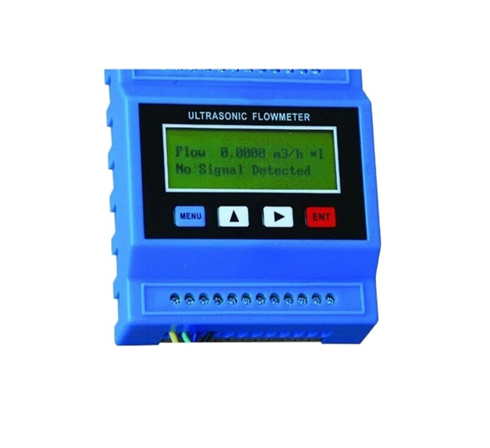
Image: Detailed wiring diagram for the TUF-2000M-TM-1 module, illustrating connections for power, signal inputs (TX, T1, T2, A13, A14, A15), outputs (OCT, Relay, AO), and communication (RS485).
- Left Side Connections:
- TX2, TX1: Transducer signal inputs.
- T2, T1: Temperature sensor inputs (for calorimeter function).
- GND: Ground connection.
- A13, A14, A15: Analog input channels (4-20mA).
- OCT+, OCT-: OCT (Open Collector Transistor) output.
- Relay+, Relay-: Relay output.
- Right Side Connections:
- GND: Ground connection.
- DN-, DN+, UP-, UP+: Transducer signal connections.
- AO: Analog Output (4-20mA).
- AO_IN: Analog Input.
- RS485-, RS485+: RS-485 communication interface.
- 24V-, 24V+: Power supply input (24V DC).
3.2 Transducer Installation
The TM-1 transducers are designed for pipes with diameters ranging from DN50mm to DN700mm. Proper installation of the transducers on the pipe is critical for accurate measurements. Ensure the pipe surface is clean and free of rust or paint. Apply coupling gel generously between the transducers and the pipe surface to ensure good acoustic contact. Mount the transducers according to the specified distance and configuration (Z-method or V-method) as detailed in the full technical manual, ensuring they are securely clamped.
4. Operating Instructions
4.1 Powering On and Basic Display
Once wired correctly and powered on (24V DC), the module's LCD display will illuminate. The display typically shows real-time flow rate, totalizer values, and other operational parameters. Use the MENU, UP, DOWN, and ENT buttons on the front panel to navigate through the menus and configure settings.

Image: The TUF-2000M-TM-1 module showing its LCD display and control buttons (MENU, UP, DOWN, ENT) for user interaction.
4.2 Configuration and Calibration
Access the configuration menu by pressing the MENU button. From here, you can set parameters such as pipe diameter, pipe material, liquid type, and transducer spacing. Initial calibration may be required to optimize accuracy for specific applications. Refer to the detailed technical manual for step-by-step calibration procedures.
4.3 Data Output and Communication
The module provides several output options:
- 4-20mA Analog Output: One channel available for transmitting flow or heat data to external devices like PLCs or data loggers.
- OCT Output: Two channels for flow or heat switching applications.
- RS-232/RS-485 Output: Isolated communication interfaces for connecting to computers or other network devices. Supports MODBUS, METER-BUS, Fuji extended, and general water meter protocols.
Ensure external devices are configured to match the module's communication settings (e.g., baud rate, parity, data bits).
5. Specifications
| Feature | Detail |
|---|---|
| Model | TUF-2000M-TM-1 |
| Measuring Range (Pipe Size) | DN50-700mm (with TM-1 transducers) |
| Liquid Temperature Range | -30°C to 90°C (with TM-1 transducers) |
| Accuracy | Flow ±1%, Heat ±2% |
| Linearity | Better than 0.5% |
| Repeatability | Better than 0.2% |
| Analog Input | 3 channels 4-20mA, 2 channels Tri-wire resistance (PT100) |
| Analog Output | 1 channel isolated 4-20mA (two-wire system) |
| Digital Output | 2 channels isolated OCT output |
| Communication Interface | Isolated RS-232/RS-485 |
| Communication Protocols | MODBUS, METER-BUS, Fuji extended, general water meter protocol |
| Product Dimensions | 3 x 2 x 1 inches |
| Item Weight | 2.65 pounds |
| Manufacturer | BUUBO |
| ASIN | B0DXDRGHTP |
| Item Model Number | 262041723 |
6. Maintenance
The BUUBO TUF-2000M-TM-1 module is designed for low maintenance. However, regular checks can ensure optimal performance and longevity:
- Cleanliness: Keep the module's display and casing clean and free from dust and debris. Use a soft, dry cloth for cleaning.
- Connections: Periodically inspect all wiring connections for tightness and signs of corrosion. Re-secure any loose connections.
- Transducer Contact: Ensure the transducers maintain good acoustic contact with the pipe. Reapply coupling gel if necessary, especially after any physical disturbance.
- Environmental Conditions: Operate the module within its specified environmental limits (temperature, humidity) to prevent damage.
7. Troubleshooting
This section provides basic troubleshooting steps for common issues. For more complex problems, consult the full technical manual or contact customer support.
- No Display/Power:
- Check the 24V DC power supply connection and ensure it is providing the correct voltage.
- Verify that the power cables are securely connected to the module.
- Inaccurate Flow Readings:
- Ensure transducers are correctly installed and spaced according to the pipe diameter and material.
- Verify that sufficient coupling gel is applied between transducers and the pipe.
- Check for air bubbles or sediment in the pipe section where transducers are mounted.
- Confirm that the pipe parameters (diameter, material) are correctly configured in the module's settings.
- No Signal Output (4-20mA, OCT, RS-485):
- Check the wiring for the respective output.
- Verify that the output settings are enabled and correctly configured in the module's menu.
- Ensure the receiving device (PLC, data logger) is correctly configured to receive the signal.
- Communication Errors:
- Verify RS-485 wiring polarity (A to A, B to B).
- Check communication parameters (baud rate, data bits, parity) on both the module and the connected device.
- Ensure proper termination resistors are used if required for the RS-485 network.
8. Warranty and Support
For warranty information, please refer to the documentation provided at the time of purchase or contact your vendor. BUUBO products are typically covered by a limited warranty against defects in materials and workmanship.
For technical support, troubleshooting assistance beyond this manual, or inquiries regarding spare parts, please contact BUUBO customer service or your authorized distributor. Have your product model number (TUF-2000M-TM-1) and purchase details ready when contacting support.