1. Introduction
This manual provides essential information for the safe and effective operation of your Jesverty DC Power Supply (SPS-12003) and Jesverty Digital Oscilloscope (JDS210). Please read this manual thoroughly before use and retain it for future reference.
2. Safety Information
Always observe the following safety precautions to prevent injury or damage to the equipment:
- Ensure proper grounding for both devices.
- Do not operate in wet or damp conditions.
- Avoid exposing the devices to direct sunlight or extreme temperatures.
- Do not open the casing; there are no user-serviceable parts inside. Refer all servicing to qualified personnel.
- Disconnect power before making any connections or disconnections.
- Use only specified power cords and accessories.
- Be aware of high voltage and current when operating the power supply.
3. Package Contents
Verify that all items are present in your package:
- 1 x Jesverty SPS-12003 DC Power Supply
- 1 x Jesverty JDS210 Digital Oscilloscope
- 1 x Power Cord for DC Power Supply
- 1 x Power Cord for Oscilloscope
- 1 x Output Cable Set for DC Power Supply (Red/Black)
- 2 x Oscilloscope Probes (100MHz)
- 1 x USB Cable (for Oscilloscope data transfer)
- 1 x User Manual (this document)
4. Product Overview
4.1 Jesverty SPS-12003 DC Power Supply
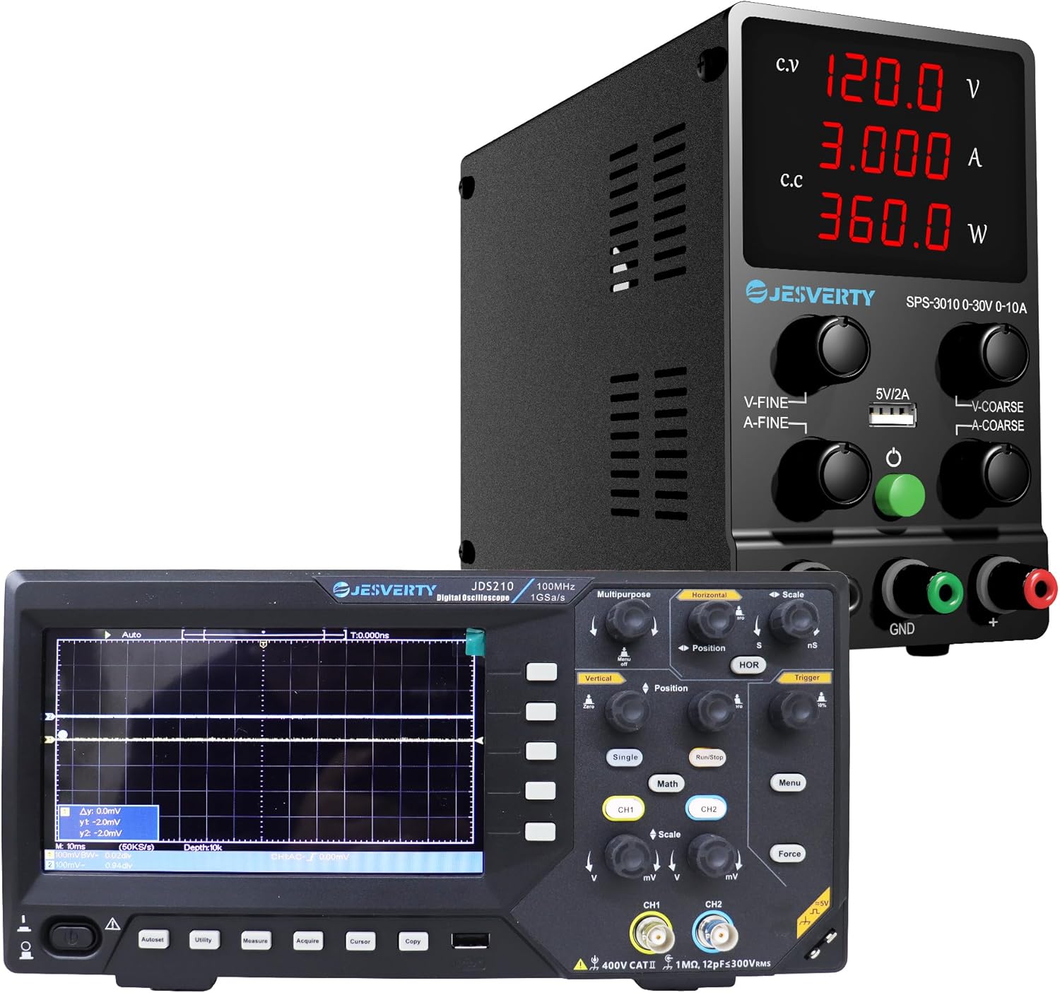
Figure 4.1: The Jesverty DC Power Supply (top) and Digital Oscilloscope (bottom) as a combined unit.

Figure 4.2: Front view of the Jesverty SPS-12003 DC Power Supply, showing the display and control knobs.

Figure 4.3: Internal view highlighting the intelligent temperature-controlled fans and radiators for extended product life and various protection features.

Figure 4.4: Detailed diagram of the Jesverty SPS-12003 DC Power Supply with numbered components and their names.
The Jesverty SPS-12003 is a variable DC power supply designed for precision applications. It features a 4-digit LED display for real-time voltage (V), current (A), and power (W) readings. It supports both Constant Voltage (C.V.) and Constant Current (C.C.) modes, automatically switching based on load changes. The unit includes coarse and fine adjustment knobs for precise control and a 5V/2A USB charging port.
Key Components (Refer to Figure 4.4):
- Voltage Display
- Current Display
- Power Display
- C.V. Mode Indicator
- C.C. Mode Indicator
- Voltage Knob (Coarse Adjustment)
- Current Knob (Coarse Adjustment)
- Voltage Knob (Fine Adjustment)
- Current Knob (Fine Adjustment)
- USB Charging Port (5V/2A)
- Output Terminal + (Red)
- Grounding Terminal (Green)
- Output Terminal - (Black)
- Power Switch
- Cooling Fan
- AC Power Inlet
- Fuse Box (Spare Fuse Inside)
4.2 Jesverty JDS210 Digital Oscilloscope

Figure 4.5: Front view of the Jesverty JDS210 Digital Oscilloscope, showing the 7-inch TFT LCD and control panel.

Figure 4.6: Side view of the Jesverty JDS210 Digital Oscilloscope, illustrating its compact design.
The Jesverty JDS210 is a dual-channel digital oscilloscope with a 100MHz bandwidth and 500 MS/s real-time sampling rate. It features a 7-inch TFT LCD (800x480 resolution) for clear waveform display. The oscilloscope supports various cursor modes for accurate measurements and offers USB storage for data transfer. It is compatible with 1X/10X/100X/1000X probes and includes auto-ranging for simplified setup.
Key Features:
- 7-inch TFT LCD (800x480 resolution)
- 100MHz Bandwidth, 2 Channels
- 500 MS/s Real-Time Sampling Rate
- 2 ns/Div to 1000s/Div Time Base Range
- 20 mV/Div~5 V/Div Vertical Scaling
- USB Drive Storage for Waveforms
- 4 Cursor Modes (ΔV, ΔT, ΔV+ΔT, auto-tracking)
- Auto-Ranging for horizontal/vertical adjustments
5. Setup
5.1 DC Power Supply (SPS-12003) Setup
- Place the power supply on a stable, level surface with adequate ventilation.
- Ensure the power switch (14) is in the OFF position.
- Connect the provided AC power cord to the AC Power Inlet (16) on the rear of the unit and then to a grounded wall outlet.
- Connect the red output cable to the Output Terminal + (11) and the black output cable to the Output Terminal - (13). If grounding is required, connect the green cable to the Grounding Terminal (12).
- Connect the other end of the output cables to your load or circuit, ensuring correct polarity.
5.2 Digital Oscilloscope (JDS210) Setup
- Place the oscilloscope on a stable, non-slip surface.
- Connect the provided AC power cord to the power input on the rear of the oscilloscope and then to a grounded wall outlet.
- Attach the oscilloscope probes to the BNC input connectors (CH1, CH2) on the front panel. Ensure the probe's ground clip is connected to the circuit's ground.
- Calibrate the probes if necessary, following the instructions in the oscilloscope's on-screen menu or a dedicated probe calibration section (not detailed here, refer to general oscilloscope usage guides).
6. Operating Instructions
6.1 Operating the DC Power Supply (SPS-12003)
- Power On: Flip the Power Switch (14) to the ON position. The LED display will illuminate.
- Setting Voltage: Use the Voltage Knob (Coarse) (6) for large adjustments and the Voltage Knob (Fine) (8) for precise adjustments. Observe the Voltage Display (1) to set the desired output voltage.
- Setting Current Limit: Use the Current Knob (Coarse) (7) and Current Knob (Fine) (9) to set the maximum output current. This acts as a safety limit to protect your circuit. Observe the Current Display (2).
- C.V. and C.C. Modes:
- When the output voltage is stable and below the set current limit, the C.V. Mode Indicator (4) will light up, indicating Constant Voltage mode.
- If the load draws more current than the set limit, the power supply will automatically switch to Constant Current (C.C.) mode, and the C.C. Mode Indicator (5) will light up. The output voltage will drop to maintain the set current.
- USB Charging Port: The 5V/2A USB Charging Port (10) can be used to charge compatible devices. This port operates independently of the main output voltage/current settings.
- Power Off: Before disconnecting the load, turn the output voltage and current knobs to their minimum settings, then flip the Power Switch (14) to the OFF position.

Figure 6.1: Illustration of the 5V/2A USB charging port on the Jesverty SPS-12003 DC Power Supply, compatible with various devices.
6.2 Operating the Digital Oscilloscope (JDS210)
- Power On: Press the power button on the front panel. The display will light up.
- Connecting Probes: Connect the probe to the BNC input (CH1 or CH2) and attach the probe tip to the test point and the ground clip to the circuit ground.
- Auto-Ranging: Press the "Auto" button for automatic adjustment of vertical and horizontal settings to display a stable waveform.
- Vertical Controls: Use the "Vertical" knobs (mV/Div, V/Div) to adjust the vertical scale (voltage per division) and "Position" to shift the waveform vertically.
- Horizontal Controls: Use the "Horizontal" knobs (ns/Div, s/Div) to adjust the horizontal scale (time per division) and "Position" to shift the waveform horizontally.
- Triggering: Adjust the "Trigger" level to stabilize the waveform display. The trigger ensures the waveform starts at a consistent point on the screen.
- Measurements: Use the "Measure" button to access automatic measurements (e.g., Vpp, Vrms, Frequency, Period). Use the "Cursor" button to enable manual cursors for precise voltage (ΔV) and time (ΔT) measurements.
- USB Storage: Connect a USB drive to the USB port on the side of the oscilloscope to save waveform data or screenshots. Use the "Copy" or "Save" function from the menu.
- Channel Selection: Use the CH1 and CH2 buttons to enable or disable channels and access their individual settings.
7. Maintenance
- Cleaning: Disconnect power before cleaning. Use a soft, dry cloth to wipe the exterior of both devices. Do not use abrasive cleaners or solvents.
- Ventilation: Ensure the cooling vents on both devices remain clear of obstructions to prevent overheating.
- Storage: Store the devices in a cool, dry place away from direct sunlight and excessive dust when not in use.
- Fuse Replacement (SPS-12003): If the power supply does not turn on, check the fuse located in the Fuse Box (17) at the rear. Replace with a fuse of the same type and rating only.
8. Troubleshooting
8.1 DC Power Supply (SPS-12003) Troubleshooting
| Problem | Possible Cause | Solution |
|---|---|---|
| No power/display | Power cord disconnected, power switch off, blown fuse. | Check power cord connection, ensure switch is ON, replace fuse if blown. |
| No output voltage/current | Output cables disconnected, voltage/current knobs set to zero, overload protection activated. | Check output cable connections, adjust knobs, reduce load or increase current limit. |
| Power supply switches to C.C. mode unexpectedly | Load current exceeds set current limit. | Increase the current limit setting or reduce the load. |
8.2 Digital Oscilloscope (JDS210) Troubleshooting
| Problem | Possible Cause | Solution |
|---|---|---|
| No waveform displayed | Probe not connected, signal too small/large, incorrect trigger settings, channel off. | Check probe connection, adjust vertical scale (mV/Div), adjust trigger level, ensure channel is enabled. |
| Unstable waveform | Incorrect trigger source or level. | Adjust trigger level, select appropriate trigger source (CH1/CH2). Use "Auto" button. |
| Distorted waveform | Probe compensation incorrect, signal exceeding input limits. | Calibrate probe compensation, adjust vertical scale. |
9. Specifications
9.1 Jesverty SPS-12003 DC Power Supply
| Parameter | Value |
|---|---|
| Output Voltage | 0-120V (Adjustable) |
| Output Current | 0-3A (Adjustable) |
| Display | 4-Digit LED (V/A/W) |
| Voltage Display Resolution | 0.01V |
| Current Display Resolution | 0.001A |
| Power Display Resolution | 0.1W |
| USB Output | 5V/2A |
| Operating Modes | Constant Voltage (C.V.), Constant Current (C.C.) |
9.2 Jesverty JDS210 Digital Oscilloscope
| Parameter | Value |
|---|---|
| Bandwidth | 100MHz |
| Channels | 2 |
| Real-Time Sampling Rate | 500 MS/s |
| Display | 7-inch TFT LCD (800x480 resolution) |
| Time Base Range | 2 ns/Div to 1000s/Div |
| Vertical Scaling | 20 mV/Div~5 V/Div |
| Storage | USB Drive (Waveforms, Screenshots) |
| Probe Compatibility | 1X/10X/100X/1000X |
10. Warranty and Support
Jesverty products are designed and manufactured to the highest quality standards. For warranty information and technical support, please refer to the warranty card included with your product or visit the official Jesverty website. Please have your model number (SPS-12003 & JDS210) and purchase date ready when contacting support.
For further assistance, you may visit the Jesverty Store on Amazon.


