1. Introduction
This manual provides essential information for the safe and efficient operation, installation, and maintenance of the ABB CM10 Universal Process Controller. The CM10 is designed for precise control and monitoring in various industrial applications, offering robust performance and versatile functionality.
Please read this manual thoroughly before installing, operating, or performing any maintenance on the device. Keep this manual accessible for future reference.
2. Safety Information
Always observe the following safety precautions to prevent injury to personnel and damage to the equipment:
- Qualified Personnel: Installation, operation, and maintenance should only be performed by qualified and trained personnel.
- Power Disconnection: Ensure the power supply is disconnected before performing any installation, wiring, or maintenance procedures.
- Electrical Safety: Adhere to all local and national electrical codes and regulations. The device operates on 100-240V AC, 50/60Hz.
- Proper Grounding: Ensure the device is properly grounded to prevent electrical shock.
- Environmental Conditions: Do not expose the controller to conditions outside its specified operating environment (e.g., extreme temperatures, excessive humidity, corrosive atmospheres).
- Original Parts: Use only genuine ABB replacement parts and accessories.
3. Product Overview
The ABB CM10 Universal Process Controller is a compact and powerful device designed for accurate process control. It features a clear display and intuitive navigation buttons for easy configuration and monitoring.
3.1 Front Panel
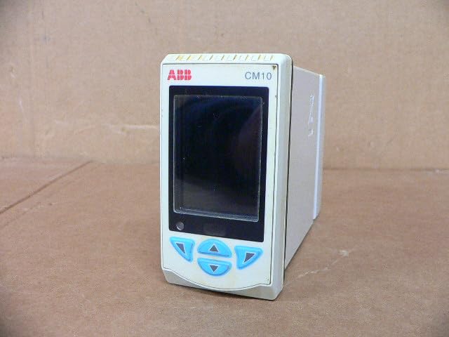
Figure 3.1: Front view of the ABB CM10 Universal Process Controller. This image shows the main display screen and the array of light blue control buttons below it, including up, down, left, right, and enter buttons.
The front panel includes the main display for process values and configuration menus, along with tactile buttons for navigation and parameter adjustment.
3.2 Rear Panel and Connections

Figure 3.2: Rear and side view of the ABB CM10 Universal Process Controller. This image highlights the multiple terminal blocks for input/output connections and printed wiring diagrams on the side casing.
The rear panel provides access to the electrical terminal blocks for connecting power, inputs (e.g., RTD, mA, mV), and outputs. Detailed wiring diagrams are typically printed on the side of the unit for reference.
3.3 Product Label
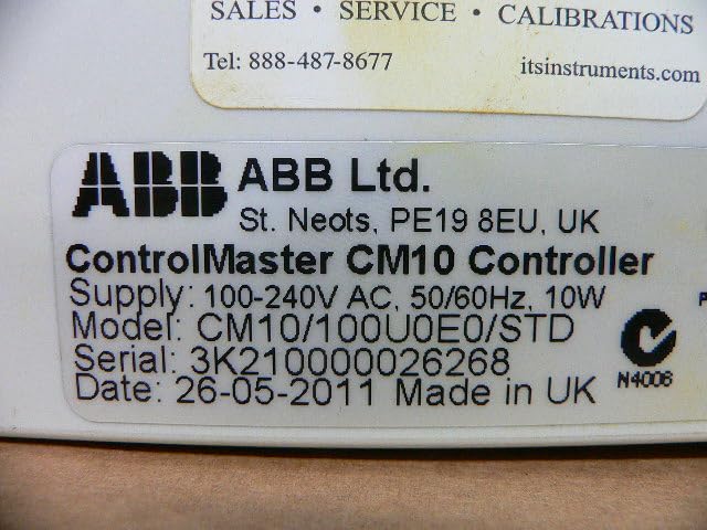
Figure 3.3: Close-up of the product label on the ABB CM10 Controller. The label clearly displays "ControlMaster CM10 Controller", supply voltage (100-240V AC, 50/60Hz, 10W), model number (CM10/100U0E0/STD), serial number, and manufacturing date.
The product label contains critical information such as the model number, serial number, power requirements, and manufacturing details. This information is essential for support and identification.
4. Setup and Installation
Proper installation is crucial for the reliable operation of the CM10 controller. Follow these steps carefully:
- Mounting: Mount the controller in a suitable panel cutout, ensuring adequate ventilation and clearance for wiring. Refer to the product's dimensional drawings for precise cutout dimensions.
- Wiring Power: Connect the 100-240V AC, 50/60Hz power supply to the designated power terminals on the rear of the unit. Ensure correct polarity and proper grounding.
- Input Wiring: Connect process inputs (e.g., thermocouples, RTDs, 4-20mA current loops, voltage signals) to the appropriate input terminals as indicated by the wiring diagrams on the unit or in detailed wiring schematics.
- Output Wiring: Connect control outputs (e.g., relays, analog outputs) to the controlled devices according to the application requirements and wiring diagrams.
- Verification: Before applying power, double-check all wiring connections for correctness, security, and insulation.
5. Operating Instructions
The CM10 controller is designed for user-friendly operation. Basic operation involves navigating menus and setting parameters.
5.1 Power On
Once all wiring is complete and verified, apply power to the unit. The controller will perform a self-test and then display the main process value screen.
5.2 Navigation
Use the front panel buttons to navigate through menus:
- Up/Down Arrows: Scroll through menu options or adjust parameter values.
- Left/Right Arrows: Move between digits when setting numerical values or navigate sub-menus.
- Enter Button: Select an option, confirm a setting, or enter a menu.
5.3 Parameter Configuration
Access the configuration menus to set control parameters such as setpoints, PID constants, alarm limits, and input/output types. Refer to the detailed programming guide (usually a separate document or advanced section of the manual) for specific parameter definitions and configuration procedures.
6. Maintenance
The ABB CM10 controller is designed for minimal maintenance. However, regular checks can ensure long-term reliability.
- Cleaning: Keep the front panel clean using a soft, damp cloth. Do not use abrasive cleaners or solvents.
- Connection Checks: Periodically inspect all electrical connections for tightness and signs of corrosion.
- Environmental Monitoring: Ensure the operating environment remains within specified limits (temperature, humidity, vibration).
- Firmware Updates: Check the ABB website for any available firmware updates that may improve performance or add features. Consult ABB technical support before performing any updates.
Note: All internal maintenance or repairs should only be performed by authorized ABB service personnel.
7. Troubleshooting
This section provides solutions to common issues encountered with the CM10 controller. For problems not listed here, contact ABB technical support.
| Problem | Possible Cause | Solution |
|---|---|---|
| Controller does not power on. | No power supply; incorrect wiring; blown fuse. | Check power connections; verify wiring against diagram; check internal fuse (if accessible and user-serviceable, otherwise contact support). |
| Display shows error message. | Input sensor fault; configuration error; internal malfunction. | Refer to the error code list in the detailed programming manual; check sensor connections; verify configuration settings; if persistent, contact support. |
| Incorrect process value reading. | Sensor calibration issue; incorrect input type configured; wiring fault. | Calibrate sensor; verify input type setting in configuration; check sensor wiring. |
8. Specifications
Key technical specifications for the ABB CM10 Universal Process Controller:
- Model: CM10/100U0E0/STD
- Supply Voltage: 100-240V AC, 50/60Hz
- Power Consumption: 10W
- Product Dimensions: 7.09 x 6.3 x 8.27 inches (180 x 160 x 210 mm)
- Weight: Approximately 1.32 Pounds (0.6 kg)
- Manufacturer: ABB Ltd.
- Date First Available: February 14, 2025
9. Warranty and Support
For specific warranty terms and conditions, please refer to the documentation provided with your purchase or contact ABB directly. Warranty periods and coverage may vary based on region and product type.
For technical support, service, or to inquire about genuine ABB replacement parts, please visit the official ABB website or contact their customer service department. You can find more information on the ABB Store on Amazon or their global support portal.


