1. Introduction
Thank you for choosing the DIY-Kit 4-Digit LED Digital Clock. This kit provides an engaging and educational experience for electronics enthusiasts, allowing you to assemble a functional digital clock with temperature display and automatic brightness adjustment. This manual will guide you through the assembly process, operation, and maintenance of your new clock.
2. Safety Information
Please read and understand all safety instructions before beginning assembly. This kit involves soldering, which requires caution.
- Soldering Safety: Always use soldering equipment in a well-ventilated area. Wear appropriate eye protection. Avoid touching the hot soldering iron tip. Allow components to cool before handling.
- Electrical Safety: Ensure the power supply is disconnected before making any connections or adjustments. Use only the specified DC 5V power source.
- Component Handling: Some electronic components can be sensitive to static electricity. Handle them carefully.
- Small Parts: This kit contains small parts that could be a choking hazard. Keep out of reach of small children.
3. Package Contents
Verify that all components listed below are present in your kit. If any parts are missing or damaged, please contact customer support.
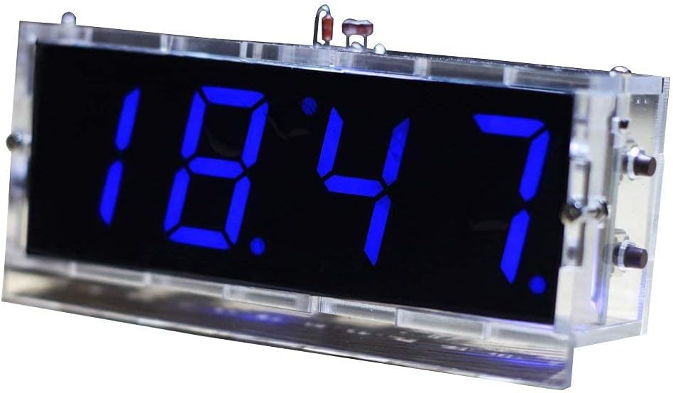
Image: All components of the DIY-Kit 4-Digit LED Digital Clock laid out, ready for assembly.
- 1x Main Printed Circuit Board (PCB)
- 4x 4-Digit LED Display Modules (Blue)
- 1x Microcontroller IC (Pre-programmed)
- 1x IC Socket
- Various Resistors (e.g., 1kΩ, 10kΩ, 330Ω)
- Various Capacitors (e.g., electrolytic, ceramic)
- Diodes (e.g., 1N4148)
- Transistors (e.g., S8050)
- Push Buttons
- 1x Photoresistor (for automatic brightness)
- 1x Thermistor (temperature sensor)
- 1x DC Power Jack
- 1x USB Power Cable
- 1x CR1220 Button Cell Holder (battery not included)
- Acrylic Case Parts
- Screws and Standoffs
4. Assembly Instructions
This kit requires basic soldering skills. Follow these steps carefully. Refer to the PCB silkscreen for component placement.
- Prepare Components: Identify all components and sort them. Pay attention to resistor values and capacitor polarities.
- Solder Smallest Components First: Begin by soldering the resistors, diodes (observe polarity, band indicates cathode), and ceramic capacitors.
- Solder Transistors and Electrolytic Capacitors: Solder the transistors (match flat side to PCB marking) and electrolytic capacitors (observe polarity, longer lead is positive).
- Solder IC Socket: Solder the IC socket onto the PCB. Ensure the notch on the socket aligns with the notch on the PCB silkscreen.
- Solder Buttons, Photoresistor, and Thermistor: Solder the push buttons, photoresistor, and thermistor into their designated spots.
- Solder DC Power Jack and USB Connector: Solder the DC power jack and the USB connector.
- Solder LED Display Modules: Carefully solder the four 4-digit LED display modules. Ensure they are flush with the PCB and correctly oriented.
- Insert Microcontroller IC: Once all soldering is complete and the PCB has cooled, carefully insert the microcontroller IC into its socket. Ensure the notch on the IC aligns with the notch on the socket and PCB. Bend the pins slightly inward if necessary to fit.
- Assemble Acrylic Case: Remove the protective film from all acrylic case parts. Assemble the case according to the provided diagrams (if any) or by matching the interlocking pieces. Secure with screws and standoffs.
- Install PCB into Case: Carefully place the assembled PCB into the acrylic case, ensuring all buttons and connectors align with the case openings. Secure the PCB within the case using the remaining screws and standoffs.
- Install CR1220 Battery: Insert a CR1220 button cell battery (not included) into the battery holder on the PCB. This battery provides backup power for timekeeping during power outages.
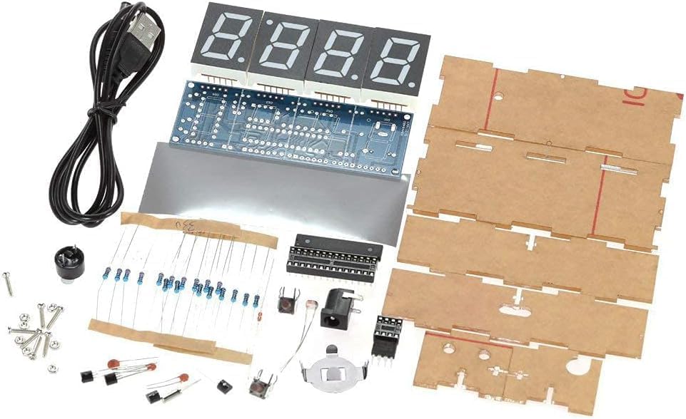
Image: The fully assembled DIY-Kit 4-Digit LED Digital Clock.
5. Operating Instructions
After successful assembly, connect the clock to a DC 5V power source using the provided USB cable and a compatible USB charger (e.g., phone charger).
5.1 Initial Power On
Upon first power-up, the clock will display a default time or a sequence of numbers. You will need to set the current time and date.
5.2 Setting Time and Date
The clock typically has multiple buttons (e.g., SET, UP, DOWN). The exact button functions may vary slightly, but the general procedure is:
- Press the SET button once to enter time setting mode. The hour digits will likely flash.
- Use the UP and DOWN buttons to adjust the hour.
- Press SET again to move to minute setting. Adjust with UP/DOWN.
- Continue pressing SET to cycle through setting seconds, year, month, day, and day of the week.
- After setting all parameters, press SET one last time to exit the setting mode.
5.3 Hourly Chime
The clock supports an hourly chime function. To enable or disable it:
- Locate the dedicated chime button or a combination of buttons (refer to specific button markings on your PCB if available).
- Pressing this button typically toggles the hourly chime on or off. An indicator (e.g., a small dot on the display) might show its status.
5.4 Temperature Display
The clock automatically displays the ambient temperature every 30 seconds. No manual action is required for this feature.
5.5 Automatic Brightness Adjustment
The integrated photoresistor allows the clock to automatically adjust its display brightness. The display will be brighter during the day and dimmer at night for optimal visibility and energy efficiency.
6. Maintenance
The DIY-Kit Digital Clock requires minimal maintenance.
- Cleaning: Use a soft, dry cloth to clean the acrylic case and display. Avoid abrasive cleaners or solvents.
- Battery Replacement: The CR1220 button cell battery provides backup for timekeeping. If the clock loses time after a power outage, replace the battery.
- Environment: Keep the clock in a dry environment, away from direct sunlight, extreme temperatures, and high humidity.
7. Troubleshooting
| Problem | Possible Cause | Solution |
|---|---|---|
| Clock does not power on. | No power, faulty connection, incorrect soldering. | Check USB cable and power adapter. Inspect all soldered joints for shorts or cold joints. Ensure IC is correctly seated. |
| Display is dim or uneven. | Faulty LED segment, incorrect resistor value, automatic brightness sensor blocked. | Check LED display soldering. Ensure photoresistor is not covered. Verify resistor values. |
| Clock loses time after power off. | CR1220 backup battery is dead or missing. | Install or replace the CR1220 button cell battery. |
| Buttons do not respond. | Incorrect soldering of buttons, faulty button. | Inspect button soldering. Test button functionality with a multimeter if possible. |
| Temperature reading is inaccurate. | Thermistor faulty or incorrectly soldered. | Check thermistor soldering and placement. |
8. Specifications
| Feature | Detail |
|---|---|
| Display Type | 4-Digit LED (Blue) |
| Display Size | 1 inch |
| Operating Voltage | DC 5V |
| Operating Current | 40mA |
| Backup Power | CR1220 Button Cell (3V, not included) |
| Case Material | Transparent Acrylic |
| Product Weight | 82 grams |
| PCB Dimensions (L x W x H) | 98 x 35 x 1.6 mm |
| Assembled Case Dimensions (L x W x H) | 105 x 46 x 29 mm |
| Features | Time, Date, Day of Week, Temperature Display, Hourly Chime, Automatic Brightness Adjustment |
9. Warranty and Support
This DIY kit is designed for educational and hobbyist purposes. Due to the nature of self-assembly and soldering, specific warranties may vary. Please refer to the retailer's return policy for information regarding defective or missing components upon receipt.
For technical support or inquiries regarding assembly, please consult online DIY electronics communities or contact the manufacturer directly if contact information is provided with your purchase.