1. Introduction
Thank you for choosing the GYZOUKA SCO-2-10M Handheld Digital Oscilloscope. This device is designed for precise waveform analysis and measurement in various applications, including home appliance repair, mobile phone maintenance, automotive troubleshooting, and electronic hobbyist projects. This manual provides essential information for the safe and effective use of your oscilloscope.
2. Safety Information
- Read all instructions carefully before operating the device.
- Do not expose the device to moisture, extreme temperatures, or direct sunlight.
- Use only the provided charging cable and accessories.
- Avoid dropping or subjecting the device to strong impacts.
- Do not attempt to disassemble or modify the oscilloscope. Refer all servicing to qualified personnel.
- Ensure proper voltage settings (X1/±40V, X10/±400V) when connecting probes to avoid damage to the device or the circuit under test.
3. Package Contents
Verify that all items are present in the package:
- 1 x Handheld Oscilloscope (SCO-2-10M)
- 2 x Red/Black Probe Clips
- 1 x Charging Cable
- 1 x User Manual
4. Product Overview
The GYZOUKA SCO-2-10M features a compact design with a 3.2-inch LCD display and intuitive controls for efficient operation.
4.1 Device Layout
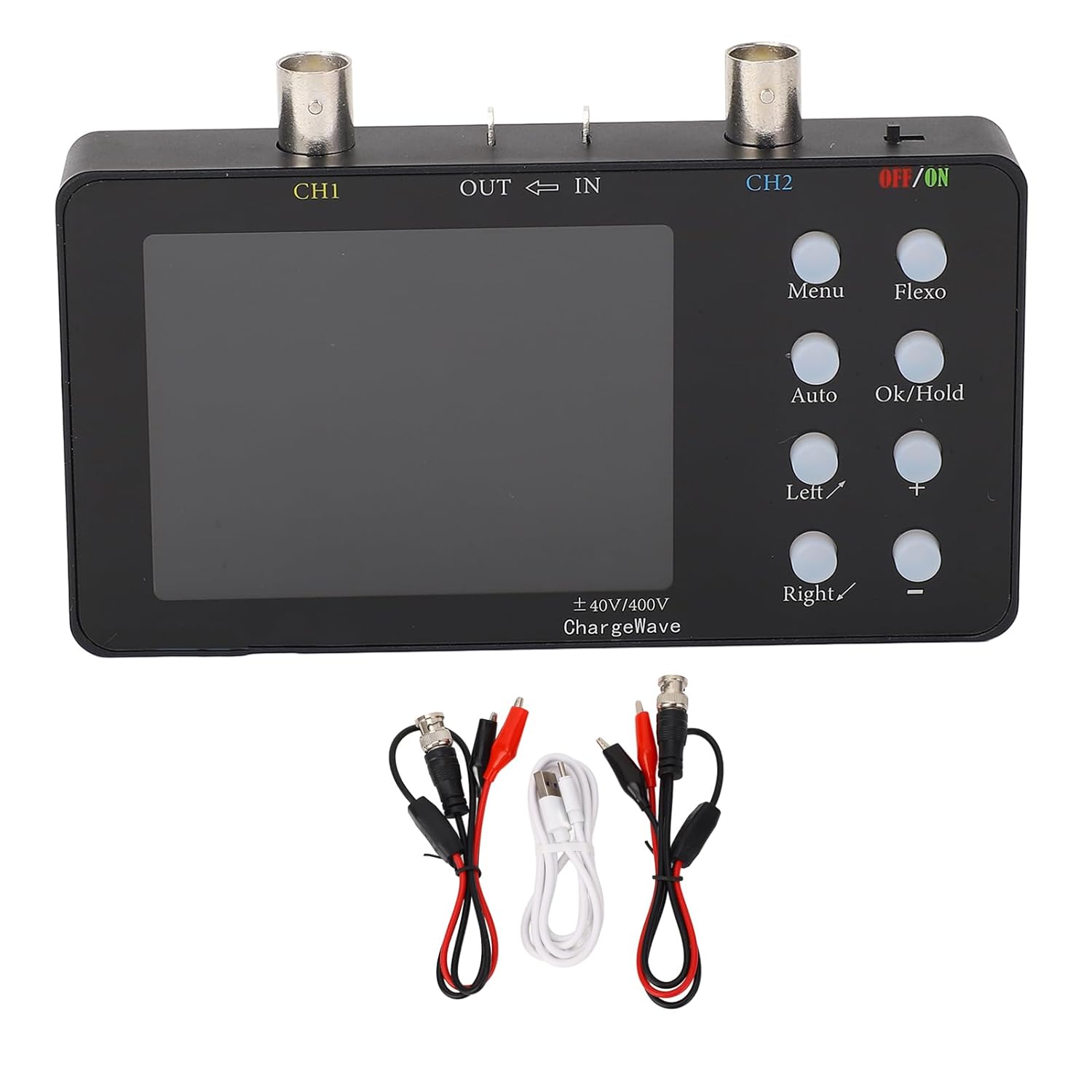
Figure 1: Front view of the oscilloscope with included accessories.
The image above shows the GYZOUKA SCO-2-10M Handheld Digital Oscilloscope. The device has a black casing with a central LCD screen. To the right of the screen are several control buttons. At the top, there are two BNC connectors labeled 'CH1' and 'CH2' for connecting probes, along with 'OUT' and 'IN' ports. A power switch labeled 'OFF/ON' is located on the top right. Below the device, two sets of red and black probe clips and a white charging cable are displayed.
4.2 Controls and Connectors

Figure 2: Angled view highlighting the control panel.
This angled view provides a closer look at the control buttons and connectors. The buttons include 'Menu', 'Flexo', 'Auto', 'Ok/Hold', 'Left/', 'Right/', '+', and '-'. These buttons are used for navigating menus, adjusting settings, and controlling waveform display. The BNC connectors for Channel 1 (CH1) and Channel 2 (CH2) are clearly visible at the top, along with the 'OUT' and 'IN' ports and the 'OFF/ON' power switch.
4.3 Key Features
- Dual Channel Design: 2 channels with 50M per channel sampling rate.
- High Storage Depth: 20K storage depth with waveform compression and expansion.
- Clear LCD Display: 3.2-inch LCD with 320x240 resolution.
- Long Endurance: Built-in 2500mAh battery for 4.5-6 hours continuous working time.
- Current Waveform Compression: Stepless compression up to 165 times for detailed analysis.
5. Setup
5.1 Charging the Device
- Connect the provided charging cable to the oscilloscope's charging port.
- Connect the other end of the charging cable to a 5V USB power adapter (not included).
- The battery indicator on the display will show charging status. A full charge provides 4.5-6 hours of continuous operation.
5.2 Connecting Probes
- Identify the BNC connectors labeled 'CH1' and 'CH2' on the top of the oscilloscope.
- Connect the BNC end of the probe clips to the desired channel connector (e.g., CH1).
- Ensure the connection is secure.
- Attach the red and black clips to the circuit points you wish to measure. The black clip is typically for ground.
6. Operating Instructions
6.1 Powering On/Off
To power on the device, slide the 'OFF/ON' switch to the 'ON' position. To power off, slide it to 'OFF'.
6.2 Basic Waveform Display

Figure 3: Dual channel oscilloscope mode displaying waveforms.
The image above illustrates the oscilloscope's display in dual channel mode, showing two distinct waveforms (one purple, one yellow) against a grid. Various measurement parameters like Max, Min, Vpp, Vavg, Vrms, and Frequency are displayed at the bottom of the screen for both channels. The 'AUTO' button can be used for automatic adjustment of the waveform display.
- Connect the probes to the circuit you wish to analyze.
- Press the 'Auto' button for automatic waveform adjustment. This will typically provide a stable display.
- Use the '+' and '-' buttons to adjust vertical sensitivity (Volts/Div) and the 'Left/' and 'Right/' buttons to adjust horizontal time base (Time/Div).
6.3 Menu Navigation
Press the 'Menu' button to access various settings and functions. Use the 'Left/', 'Right/', '+', and '-' buttons to navigate through menu options and adjust values. Press 'Ok/Hold' to confirm selections or hold the current waveform.
6.4 Waveform Storage and Compression
The oscilloscope supports 20K storage depth. This allows for detailed capture and analysis of waveforms. The device also offers stepless compression of current waveforms up to 165 times, enabling detailed examination of current variation curves at any compression level. Access these features through the 'Menu' options.
6.5 Voltage and Current Measurement
The device supports voltage measurement (X1/±40V, X10/±400V) and current measurement (0-6A with a minimum accuracy of 2mA). Ensure the correct probe settings and input impedance (1MΩ) are selected for accurate readings. Specific measurement parameters are displayed on the screen.
7. Maintenance
- Cleaning: Use a soft, dry cloth to clean the device. Do not use abrasive cleaners or solvents.
- Storage: Store the oscilloscope in a cool, dry place away from direct sunlight and extreme temperatures.
- Battery Care: For prolonged storage, charge the battery to approximately 50% every few months to maintain battery health.
- Firmware: The device supports firmware upgrades. Check the manufacturer's website for updates and instructions.
8. Troubleshooting
- Device does not power on: Ensure the battery is charged. Connect the charging cable and try again.
- No waveform displayed: Check probe connections. Ensure the input signal is within the device's measurement range. Press 'Auto' to attempt automatic waveform detection.
- Unstable waveform: Adjust the trigger settings (level, mode) in the menu. Ensure proper grounding.
- Inaccurate readings: Verify probe attenuation settings (X1/X10) match the physical probe. Ensure correct voltage range is selected.
9. Specifications
| Feature | Specification |
|---|---|
| Model | SCO-2-10M |
| Sampling Rate | 50M/Channel |
| Channels | 2 |
| Analog Bandwidth | 10MSa/s (per channel) |
| Voltage Measurement | X1/±40V, X10/±400V |
| Input Impedance | 1MΩ |
| Storage Depth | 20Kb |
| Parameter Display | 12 Types |
| Current Measurement | 0-6A |
| Minimum Current Accuracy | 2mA |
| Current Sampling Rate | 2.5KSa/s |
| Display | 3.2 inch LCD, Resolution 320x240 |
| Charging Voltage | 5V |
| Battery Capacity | 1 x 2500mAh Li Battery (built-in) |
| Continuous Working Time | 4.5-6 hours |
| Firmware Upgrade | Support |
| Item Model Number | GYZOUKAio8xper6gc |
| Package Dimensions | 9.06 x 6.3 x 1.97 inches |
| Item Weight | 11.25 ounces |
10. Warranty and Support
For warranty information and technical support, please refer to the contact details provided with your purchase or visit the official GYZOUKA website. Keep your purchase receipt as proof of purchase for warranty claims.


