
ANCEL AD530, PB600
ANCEL AD530 OBD2 Scanner Diagnostic Tool & PB600 Power Circuit Probe Tester
User Manual
1. Introduction
This manual provides comprehensive instructions for the operation, maintenance, and troubleshooting of your ANCEL AD530 OBD2 Scanner Diagnostic Tool and ANCEL PB600 Power Circuit Probe Tester. These devices are designed to assist automotive professionals and DIY enthusiasts in diagnosing vehicle issues and testing electrical circuits efficiently and accurately.
2. Product Overview
2.1 ANCEL AD530 OBD2 Scanner Diagnostic Tool
The ANCEL AD530 is an advanced OBD2 scanner designed for comprehensive vehicle diagnostics. It offers a wide range of functions beyond basic code reading, including real-time data display, battery voltage testing, and I/M readiness checks.

Figure 2.1: ANCEL AD530 OBD2 Scanner Diagnostic Tool. This image shows the front view of the AD530 scanner with its display screen and navigation buttons.
- Enhanced OBD2 Scanner: Provides real-time testing of 12V battery voltage and deeper insights into vehicle issues.
- All-in-One Diagnostic Tool: Reads and clears fault codes, resets monitors, graphs live data, displays freeze frame info, runs EVAP, O2 sensor, and on-board monitoring tests, checks I/M readiness, and retrieves VIN.
- Live Data Tracking: Visualizes real-time performance data such as RPM, sensor voltage, and engine temperature.
- Intelligent Battery Health Guardian: Functions as a reliable car battery tester with real-time voltage graphs.
2.2 ANCEL PB600 Power Circuit Probe Tester
The ANCEL PB600 is a versatile automotive electrical circuit tester designed for diagnosing electrical systems. It combines multiple functions including circuit testing, battery testing, relay testing, injector testing, and oscilloscope capabilities.
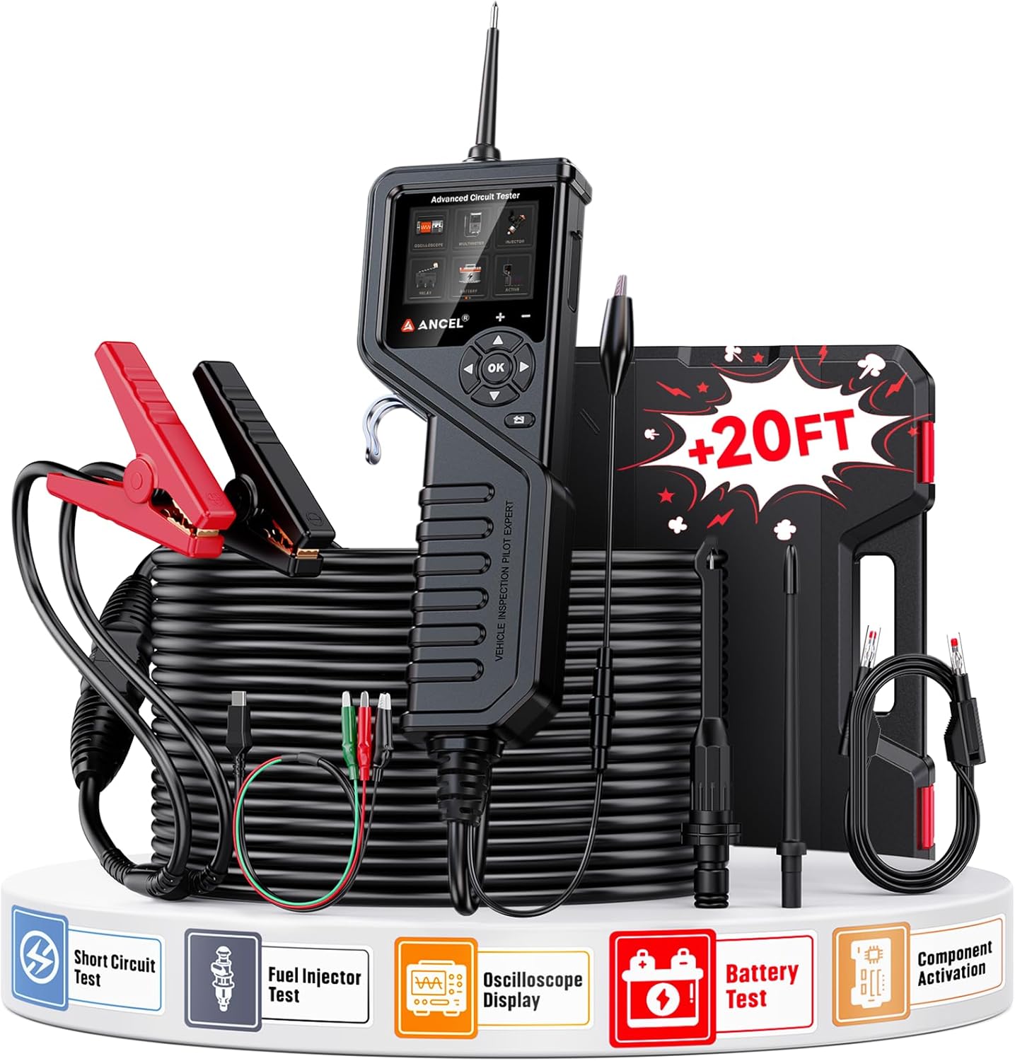
Figure 2.2: ANCEL PB600 Power Circuit Probe Tester. This image displays the PB600 unit with its probe, cables, and alligator clips, ready for electrical testing.
- Multi-functional Tester: Performs short circuit tests, fuel injector tests, oscilloscope display, battery tests, and component activation.
- Wide Voltage Range: Operates within an 8-35V automotive electrical circuit.
- Comprehensive Electrical Diagnostics: Includes DC/AC voltage test, frequency test, duty cycle test, resistance & diode test, injector signal test, cranking test, relay test, and charging test.
3. Setup
3.1 ANCEL AD530 Setup
- Locate the vehicle's 16-pin Data Link Connector (DLC), usually under the dashboard.
- Ensure the vehicle's ignition is OFF.
- Connect the AD530's OBD2 cable to the vehicle's DLC.
- Turn the vehicle's ignition to the ON position (engine can be off). The AD530 will power on automatically.
- Select the desired language and unit settings from the "Setup" menu if this is the first use.
3.2 ANCEL PB600 Setup
- Connect the red power clip to the vehicle's positive (+) battery terminal.
- Connect the black ground clip to the vehicle's negative (-) battery terminal or a good chassis ground.
- The PB600 will power on. Ensure the display shows a stable voltage reading.
- For specific tests, connect the probe tip to the circuit or component to be tested.
4. Operating Instructions
4.1 Using the ANCEL AD530
The AD530 offers various diagnostic functions accessible via its main menu.
- Read Codes: Select "OBDII" > "Read Codes" to view current, pending, and permanent diagnostic trouble codes (DTCs).
- Erase Codes: After repairs, select "OBDII" > "Erase Codes" to clear DTCs and turn off the Check Engine Light. Ensure the ignition is ON and engine is OFF before erasing codes.
- Live Data: Select "OBDII" > "Data Stream" to view real-time sensor data. Data can be displayed in text or graph format.
- I/M Readiness: Select "I/M" to check the status of emission-related monitors. This is useful for pre-smog checks.
- Battery Test: Select "BAT" to perform a 12V battery voltage test and view its real-time graph.
- DTC Lookup: Use the "Lookup" function to get detailed descriptions of DTCs.

Figure 4.1: ANCEL AD530 Full OBD2 Functions. This image illustrates the various OBD2 functions available on the AD530, including Read Codes, Erase Codes, Live Data, and I/M Readiness.
4.2 Using the ANCEL PB600
The PB600's intuitive interface allows for quick selection of various testing modes.
- DC Voltage Test: Touch the probe tip to a circuit to read its DC voltage.
- AC Voltage Test: Select AC mode and touch the probe to an AC circuit.
- Resistance Test: Measure the resistance of components.
- Diode Test: Check the functionality of diodes.
- Continuity Test: Verify circuit continuity.
- Component Activation: Apply positive or negative battery voltage to components like motors, lights, or relays to test their function. Use caution to avoid short circuits.
- Fuel Injector Test: Test the pulse signal of fuel injectors.
- Relay Test: Test the operation of various automotive relays.
- Oscilloscope Display: View waveform signals for detailed electrical analysis.

Figure 4.2: ANCEL PB600 All-in-One Super Probe Circuit Tester. This image highlights the comprehensive testing capabilities of the PB600, including voltage, frequency, resistance, and component activation tests.
5. Maintenance
- Clean the device casings with a soft, damp cloth. Do not use abrasive cleaners or solvents.
- Store the tools in a dry, cool environment, away from direct sunlight and extreme temperatures.
- Keep cables and connectors free from kinks or damage.
- Regularly check the probe tip of the PB600 for wear and tear.
- Ensure the AD530's software is updated periodically for optimal performance and compatibility with newer vehicles. Refer to the ANCEL website for update instructions.
6. Troubleshooting
| Problem | Possible Cause | Solution |
|---|---|---|
| AD530 does not power on. | Loose OBD2 connection; Vehicle ignition OFF; Vehicle battery low. | Ensure secure connection; Turn ignition ON; Check vehicle battery. |
| AD530 displays "Link Error". | Faulty connection; Non-OBD2 compliant vehicle; Damaged cable. | Check connection; Verify vehicle compatibility; Try another OBD2 port if available. |
| PB600 does not power on. | Incorrect battery connection; Vehicle battery dead. | Verify red clip to positive, black to negative; Check vehicle battery voltage. |
| Inaccurate readings on PB600. | Poor probe contact; Corroded terminals; Incorrect mode selected. | Ensure firm contact; Clean terminals; Select appropriate test mode. |
7. Specifications
7.1 ANCEL AD530 Specifications
- Display: Color LCD
- Operating Voltage: 9-18V DC (via OBD2 DLC)
- Supported Protocols: All OBDII/EOBD protocols (CAN, J1850 PWM, J1850 VPW, ISO9141, KWP2000)
- Functions: Read/Clear DTCs, Live Data, Freeze Frame, I/M Readiness, O2 Sensor Test, On-Board Monitor Test, EVAP System Test, Vehicle Information, Battery Voltage Test.
7.2 ANCEL PB600 Specifications
- Operating Voltage: 8-35V DC
- Display: Color LCD
- Cable Length: Approximately 20 feet (6 meters)
- Functions: DC/AC Voltage Test, Frequency Test, Duty Cycle Test, Resistance Test, Diode Test, Continuity Test, Component Activation, Fuel Injector Test, Relay Test, Cranking Test, Charging Test, Oscilloscope Display.
8. Warranty and Support
ANCEL products are designed for reliability and performance. For warranty information, technical support, or service inquiries, please refer to the official ANCEL website or contact their customer service department. Keep your purchase receipt as proof of purchase for warranty claims.
Official ANCEL Website: www.anceltech.com
Ask a question about this manual
Ask about setup, troubleshooting, compatibility, parts, safety, or missing instructions. Manuals+ will review the question and use this page’s manual context to help answer it.