1. Product Overview
The Mastech MS850D is a 6000-count True RMS auto-ranging digital multimeter designed for precise electrical measurements. It is suitable for professionals, technicians, and enthusiasts, offering a wide range of functions for various electrical applications.

Figure 1: Front view of the Mastech MS850D Digital Multimeter, displaying a measurement of 198.7 mV.
Key Features:
- 6000 Counts Auto Ranging: Provides precise measurements across various ranges automatically.
- True RMS: Ensures accurate readings for non-sinusoidal AC waveforms.
- Comprehensive Measurement Capabilities: Measures AC/DC Voltage, AC/DC Current, Resistance, Capacitance, Frequency, and Temperature.
- Safety Certified: CAT III 600V rating for safe use in electrical testing environments.
- User-Friendly Functions: Includes Buzzer/Continuity, Diode Test, Transistor Test (optional), MAX/MIN, REL, Non-Contact Voltage (NCV) Detection, Live Wire Recognition, Data Hold, Flashlight, and Auto Power Off.
- Compact Design: Ergonomic dimensions (150mm x 75mm x 47mm) and lightweight (284g) for easy handling.
2. Package Contents
Verify that all items listed below are included in your package:
- 1 x Mastech MS850D-6000 Counts True RMS Auto Ranging Digital Multimeter
- 1 x Temperature probe
- 1 x Pair of Test leads
- 2 x Batteries (AAA type, 1.5V)
- 1 x User Manual
3. Safety Information
WARNING: To avoid electric shock or personal injury, read all safety information before using this product. Use the multimeter only as specified in this manual; otherwise, the protection provided by the multimeter may be impaired.
- Always ensure the multimeter is in good working condition before use.
- Do not apply more than the rated voltage, as marked on the multimeter, between the terminals or between any terminal and earth ground. The MS850D is rated for CAT III 600V.
- Use caution when working with voltages above 30V AC RMS, 42V peak, or 60V DC. These voltages pose a shock hazard.
- Do not use the multimeter if the test leads are damaged or if the meter appears damaged.
- Ensure the rotary switch is in the correct position for the measurement you intend to make.
- Never connect the test leads to a voltage source when the rotary switch is set to current, resistance, or continuity mode.
- Replace the battery and fuses only with the specified type and rating.
- Do not operate the multimeter in explosive gas, vapor, or dusty environments.
- Keep fingers behind the finger guards on the test probes during measurements.
4. Setup
4.1 Battery Installation
The MS850D multimeter requires two 1.5V AAA batteries for operation. To install or replace batteries:
- Ensure the multimeter is powered off and disconnect all test leads.
- Locate the battery compartment cover on the back of the multimeter.
- Use a screwdriver to loosen the screw securing the battery cover.
- Remove the cover and insert the two AAA batteries, observing the correct polarity (+ and -).
- Replace the battery cover and tighten the screw.
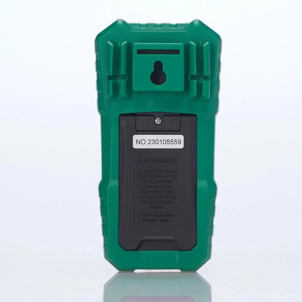
Figure 2: Rear view of the multimeter, illustrating the battery compartment and safety warnings.
4.2 Connecting Test Leads
Proper connection of test leads is essential for accurate and safe measurements.
- Insert the black test lead into the COM (Common) input jack.
- For most voltage, resistance, continuity, capacitance, frequency, and temperature measurements, insert the red test lead into the VΩmA input jack.
- For current measurements up to 600mA, insert the red test lead into the VΩmA input jack.
- For current measurements between 600mA and 10A, insert the red test lead into the 10A MAX input jack.

Figure 3: Angled view of the multimeter, highlighting the input jacks for test leads.
5. Operating Instructions
This section details how to use the Mastech MS850D for various measurements.
5.1 Powering On/Off
Rotate the central dial from the "OFF" position to any desired measurement function to power on the multimeter. To power off, rotate the dial back to the "OFF" position.
5.2 Rotary Switch Functions
The rotary switch selects the primary measurement function:
- V~ (AC Voltage): Measures alternating current voltage.
- V- (DC Voltage): Measures direct current voltage.
- Hz/% (Frequency/Duty Cycle): Measures frequency and duty cycle.
- Ω (Resistance): Measures electrical resistance.
- Continuity/Diode: Checks for circuit continuity and tests diodes.
- NCV/Live: Non-Contact Voltage detection and Live Wire recognition.
- °C/°F (Temperature): Measures temperature using the included probe.
- hFE (Transistor Test): Measures transistor gain (requires optional socket).
- μA~ / μA- (AC/DC Microamperes): Measures microampere current.
- mA~ / mA- (AC/DC Milliamperes): Measures milliampere current.
- A~ / A- (AC/DC Amperes): Measures ampere current (up to 10A).
5.3 Button Functions
- SEL (Select): Toggles between different functions within a single rotary switch position (e.g., AC/DC voltage, continuity/diode, °C/°F).
- HOLD: Freezes the current reading on the display. Press again to release.
- MIN/MAX/REL:
- Press once to enter MIN/MAX mode. The multimeter will record the minimum and maximum values. Press again to cycle between MIN, MAX, and current reading.
- Long press to activate REL (Relative) mode. This subtracts the current reading from all subsequent readings, useful for measuring changes.
- Flashlight Button (often combined with backlight): Activates the built-in flashlight for illuminating the measurement area.
5.4 Specific Measurement Procedures
5.4.1 Voltage Measurement (AC/DC)
- Set the rotary switch to V~ for AC voltage or V- for DC voltage. Use the SEL button to switch between AC and DC if the position combines them.
- Connect the black test lead to the COM jack and the red test lead to the VΩmA jack.
- Connect the test probes in parallel across the circuit or component to be measured.
- Read the voltage value on the display.
5.4.2 Current Measurement (AC/DC)
CAUTION: Never connect the multimeter in parallel with a voltage source when measuring current. Always connect in series with the load.
- Determine if the current is AC or DC.
- Set the rotary switch to the appropriate current range (μA, mA, or A). Use the SEL button to switch between AC and DC.
- Connect the black test lead to the COM jack.
- For currents up to 600mA, connect the red test lead to the VΩmA jack. For currents up to 10A, connect the red test lead to the 10A MAX jack.
- Open the circuit where the current is to be measured and connect the multimeter in series.
- Read the current value on the display.
5.4.3 Resistance Measurement
- Set the rotary switch to the Ω position.
- Connect the black test lead to the COM jack and the red test lead to the VΩmA jack.
- Ensure the circuit or component is de-energized before measuring resistance.
- Connect the test probes across the component.
- Read the resistance value on the display.
5.4.4 Continuity Test
- Set the rotary switch to the Continuity/Diode position. Use SEL to select continuity mode (usually indicated by a speaker icon).
- Connect the black test lead to the COM jack and the red test lead to the VΩmA jack.
- Connect the test probes across the circuit or component.
- If the resistance is below approximately 50Ω, the buzzer will sound, indicating continuity.
5.4.5 Diode Test
- Set the rotary switch to the Continuity/Diode position. Use SEL to select diode mode (usually indicated by a diode symbol).
- Connect the black test lead to the COM jack and the red test lead to the VΩmA jack.
- Connect the red probe to the anode and the black probe to the cathode of the diode. The display will show the forward voltage drop.
- Reverse the probes. The display should show "OL" (Open Loop) for a good diode.
5.4.6 Capacitance Measurement
- Set the rotary switch to the Capacitance position (often combined with Hz/% or other functions, use SEL to select).
- Connect the black test lead to the COM jack and the red test lead to the VΩmA jack.
- Ensure the capacitor is fully discharged before measurement to prevent damage to the multimeter.
- Connect the test probes across the capacitor terminals.
- Read the capacitance value on the display.
5.4.7 Frequency Measurement
- Set the rotary switch to the Hz/% position. Use SEL to select frequency mode.
- Connect the black test lead to the COM jack and the red test lead to the VΩmA jack.
- Connect the test probes across the signal source.
- Read the frequency value on the display.
5.4.8 Temperature Measurement
- Set the rotary switch to the °C/°F position. Use SEL to switch between Celsius and Fahrenheit.
- Connect the temperature probe to the COM and VΩmA jacks, observing polarity if specified by the probe.
- Place the tip of the temperature probe on or near the object whose temperature is to be measured.
- Read the temperature value on the display.
5.4.9 Non-Contact Voltage (NCV) Detection
- Set the rotary switch to the NCV/Live position.
- Move the top front part of the multimeter close to the conductor or outlet.
- The multimeter will emit an audible beep and the NCV indicator light will flash if AC voltage is detected, with the frequency of beeps and flashes increasing with voltage strength.
6. Maintenance
Proper maintenance ensures the longevity and accuracy of your multimeter.
6.1 Cleaning
- Wipe the case with a damp cloth and mild detergent. Do not use abrasives or solvents.
- Keep the input terminals free of dirt and moisture.
6.2 Battery Replacement
Refer to Section 4.1 for detailed instructions on battery replacement. Replace batteries when the low battery indicator appears on the display.
6.3 Fuse Replacement
If the current measurement function fails, the fuse may need replacement. The MS850D uses two fuses:
- F1: F300mA/250V (for mA/μA range)
- F2: F10A/250V (for 10A range)
To replace fuses:
- Ensure the multimeter is powered off and disconnect all test leads.
- Open the battery compartment cover (refer to Section 4.1).
- Carefully remove the old fuse(s) and replace with new fuses of the exact same type and rating.
- Replace the battery cover and tighten the screw.
7. Troubleshooting
If you encounter issues with your Mastech MS850D, refer to the following common problems and solutions:
| Problem | Possible Cause | Solution |
|---|---|---|
| No display or dim display | Low or dead batteries | Replace batteries (refer to Section 4.1). |
| Incorrect readings | Incorrect function selected; Loose test leads; Damaged test leads; Out of range measurement | Verify rotary switch position; Ensure test leads are securely connected; Inspect test leads for damage; Check if the measurement is within the multimeter's specified range. |
| Current measurement not working | Blown fuse | Replace the appropriate fuse (refer to Section 6.3). |
| "OL" (Overload) displayed | Measurement exceeds the selected range or multimeter's maximum capacity | Select a higher range if available, or confirm the measurement is within the multimeter's limits. |
8. Specifications
Detailed technical specifications for the Mastech MS850D Digital Multimeter:

Figure 4: Detailed specifications and packaging information for the Mastech MS850D.
| Measurement | Range | Accuracy |
|---|---|---|
| DC Voltage | 600mV, 6V, 60V, 600V | ±(0.8%+5) |
| AC Voltage | 600mV, 6V, 60V, 600V | ±(1.0%+10) |
| DC Current | 600μA, 6000μA, 60mA, 600mA, 6A, 10A | ±(2.0%+5) (μA/mA), ±(3.0%+5) (A) |
| AC Current | 600mA, 6A, 10A | ±(2.5%+5) (mA), ±(3.0%+5) (A) |
| Resistance | 600Ω, 6KΩ, 60KΩ, 600KΩ, 6MΩ, 60MΩ | ±(1.0%+5) (600Ω-6MΩ), ±(1.2%+5) (60MΩ) |
| Capacitance | 60nF, 600nF, 6μF, 60μF, 600μF, 6mF, 60mF, 100mF | ±(4.0%+25) (60nF-600μF), ±(5.0%+25) (6mF-100mF) |
| Frequency | 10Hz, 100Hz, 1KHz, 10KHz, 100KHz, 1MHz, 10MHz | ±(0.5%+4) |
| Temperature | -20°C to 0°C, 0°C to 400°C, 400°C to 1000°C | ±(4°C), ±(3.0%+3), ±(2.0%+3) |
| Display | 6000 Counts | |
| Safety Rating | CAT III 600V | |
| Power Source | 2 x 1.5V AAA Batteries | |
| Dimensions (L x W x H) | 150mm x 75mm x 47mm (approx.) | |
| Weight | 284g (approx.) | |
9. Warranty and Support
The Mastech MS850D Digital Multimeter is manufactured by Mastech and imported by REES52. For warranty information, technical support, or service inquiries, please refer to the warranty card included with your product or contact the seller/manufacturer directly.
Please retain your proof of purchase for warranty claims.
- Manufacturer: Mastech
- Importer: REES52
- Model Number: MS850D


