
1. Introduction
This manual provides comprehensive instructions for the installation, operation, and maintenance of the Aoleaby XR20CX-4N1F1 Temperature Controller. This device is designed for precise temperature control in cold storage, refrigerators, and similar applications, ensuring stable and reliable performance.
Key features include a user-friendly interface, fast response capability, high stability for long-term operation, and data recording/analysis functions with support for data export.
2. Product Overview

Figure 2.1: Front view of the XR20CX-4N1F1 Temperature Controller, showing the digital display and control buttons.

Figure 2.2: Angled front view of the XR20CX-4N1F1, providing a clearer perspective of the control panel.
The XR20CX-4N1F1 features a clear digital display for temperature readings and status indicators. Control is managed via a set of intuitive buttons on the front panel, including buttons for light, defrost, setpoint adjustment, navigation, and power.
3. Setup and Installation
3.1 Unpacking and Components
Carefully unpack the temperature controller and verify that all components are present:
- XR20CX-4N1F1 Temperature Controller unit
- Temperature probes (NTC type)
- Mounting clips
Video 3.1: An overview of the XR20CX-4N1F1 Temperature Controller, showcasing its components and general instructions for use. This video highlights product details and compatibility.
3.2 Mounting
The controller is designed for panel mounting. Ensure the mounting hole dimensions are appropriate for the unit. Secure the controller using the provided mounting clips.
3.3 Wiring
WARNING: All wiring should be performed by a qualified electrician and in accordance with local electrical codes. Disconnect power before making any connections.
The XR20CX-4N1F1 has two NTC probe inputs: one for temperature control and another for defrost termination temperature and fan management. It also features configurable digital inputs.
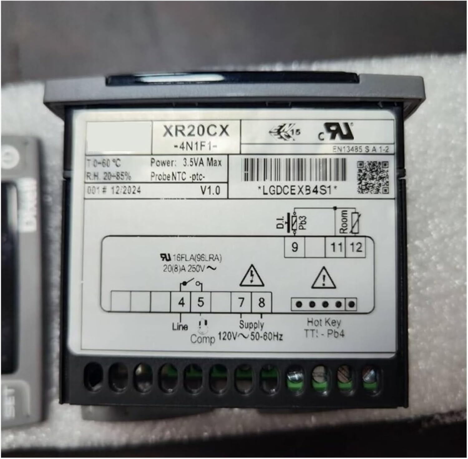
Figure 3.1: Back view of the XR20CX-4N1F1, illustrating the wiring terminals and product label with electrical specifications.
Refer to the label on the back of the unit (Figure 3.1) for specific terminal connections. Typical connections include:
- Line: Power input (e.g., 120V~ 50-60Hz)
- Comp: Compressor output
- Supply: Additional power supply connections
- Room: Room temperature probe input
- TT: Defrost termination probe input
Ensure all connections are secure and properly insulated.
4. Operating Instructions
4.1 Basic Controls
The front panel features the following buttons:
- 💡 (Light): Activates/deactivates the internal light (if connected).
- ❄️ (Defrost): Initiates a manual defrost cycle.
- SET: Enters parameter setting mode or confirms a value.
- ▲ (Up Arrow): Increases values or navigates through menus.
- ▼ (Down Arrow): Decreases values or navigates through menus.
- Ⓜ (Power): Turns the unit ON/OFF or exits parameter setting mode without saving.
4.2 Setting the Temperature Setpoint
- Press the SET button once. The current setpoint value will flash on the display.
- Use the ▲ or ▼ buttons to adjust the setpoint to the desired temperature.
- Press the SET button again to confirm and save the new setpoint.
4.3 Advanced Parameter Settings
To access advanced parameters (e.g., defrost intervals, differential, probe calibration), refer to the detailed parameter list provided in the full technical manual. Typically, this involves holding the SET button for several seconds to enter the parameter menu, then using the arrow keys to navigate and adjust values.
5. Maintenance
5.1 Cleaning
Regularly clean the front panel of the controller with a soft, damp cloth. Do not use abrasive cleaners or solvents, as these can damage the display or buttons. Ensure no liquid enters the unit.
5.2 Probe Inspection
Periodically inspect the temperature probes for any signs of damage or corrosion. Ensure they are securely placed in their intended locations for accurate temperature readings. Replace damaged probes promptly.
6. Troubleshooting
This section addresses common issues you might encounter with the XR20CX-4N1F1 Temperature Controller.
| Problem | Possible Cause | Solution |
|---|---|---|
| Display shows 'HH' or 'LL' | Temperature probe error (open or short circuit) or temperature out of range. | Check probe connections. Replace faulty probe if necessary. Ensure ambient temperature is within the controller's operating range. |
| Controller not responding | No power supply or incorrect wiring. | Verify power connection and voltage. Check all wiring according to the diagram. |
| Temperature reading inaccurate | Probe placement, calibration error, or faulty probe. | Ensure probe is correctly positioned. Check probe calibration settings. Replace probe if damaged. |
| Compressor not turning on/off | Setpoint not reached, differential setting, or relay fault. | Verify setpoint and differential settings. Check compressor wiring. Consult a technician if relay is suspected faulty. |
If the problem persists after attempting these solutions, contact qualified technical support.
7. Specifications
The following are the general specifications for the Aoleaby XR20CX-4N1F1 Temperature Controller:
- Model: XR20CX-4N1F1
- Power Supply: 120V~ 50-60Hz (as indicated on the unit's label)
- Power Consumption: 3.5VA Max
- Probe Type: NTC
- Temperature Range: T 0~60°C (Operating environment)
- Relative Humidity: R.H. 20~85% (Operating environment)
- Compressor Relay: 16FLA (96LRA) 20(8)A 250V~
- Package Dimensions: 1.18 x 0.79 x 0.39 inches
- Item Weight: 1.32 pounds
8. Warranty and Support
For warranty information and technical support, please refer to the documentation provided at the time of purchase or contact your vendor directly. Keep your purchase receipt as proof of purchase.