
1. Introduction
This manual provides detailed instructions for the installation, operation, and maintenance of the Agatige 96-UIF Multi-Function Meter. This device is designed for precise measurement and display of electrical parameters in 3-phase systems, including voltage, current, frequency, active power, reactive power, apparent power, and power factor. It is suitable for applications in substation automation, distribution automation, and intelligent building systems.
Please read this manual thoroughly before using the product to ensure correct operation and to prevent damage.
2. Safety Information
Observe the following safety precautions to prevent injury and damage to the device:
- Installation and maintenance should only be performed by qualified personnel.
- Ensure the power supply is disconnected before performing any wiring or maintenance.
- Verify all connections are secure and correct according to the wiring diagrams.
- Do not operate the meter in environments exceeding its specified operating conditions (temperature, humidity).
- Avoid exposing the device to direct sunlight, excessive dust, or corrosive gases.
- The meter is designed for indoor use only.
3. Package Contents
Upon unpacking, please verify that all items listed below are present and undamaged:
- 1 x Agatige 96-UIF Multi-Function Meter
- 3 x Green Terminal Modules
- 2 x Transparent Mounting Accessories
- 2 x Screws
- 1 x User Manual (this document)

Image 3.1: Agatige 96-UIF Multi-Function Meter with green terminal modules and transparent mounting accessories.
4. Product Overview
The Agatige 96-UIF is a compact digital meter designed for comprehensive electrical parameter monitoring. It features a clear LED display and intuitive navigation buttons.

Image 4.1: Front view of the Agatige 96-UIF Multi-Function Meter, showing the display and control buttons.

Image 4.2: Detailed front view highlighting the LED display and navigation buttons (left arrow, right arrow, Menu, Enter).
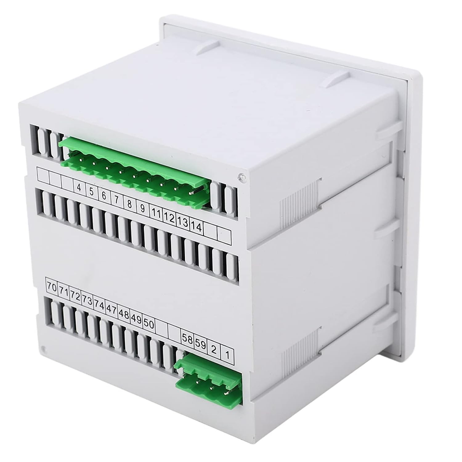
Image 4.3: Rear view of the meter, illustrating the various terminal blocks for input, output, and communication connections.

Image 4.4: Side profile of the meter, showing its compact form factor.
4.1. Key Features
- Measures Voltage, Current, Frequency, Active Power, Reactive Power, Apparent Power, Power Factor.
- RMS measurement with accuracy class 0.5.
- Programmable 2, 3, or 4 rows of LED display.
- RS-485 digital interface with MODBUS-RTU protocol.
- 2 channels of energy pulse output (optocoupler isolation).
- Wide working range: AC, DC80~270V.
5. Setup and Installation
Proper installation is crucial for the accurate and safe operation of the meter. Follow these steps carefully:
5.1. Mounting the Meter
- Prepare a panel cutout of appropriate dimensions for the meter (refer to specifications for exact size).
- Insert the meter into the cutout from the front of the panel.
- Secure the meter using the provided transparent mounting accessories and screws from the rear of the panel. Ensure it is firmly seated.
5.2. Wiring Connections
All wiring must be performed with the power supply disconnected. Refer to the wiring diagram for your specific application (e.g., 3-phase 3-wire, 3-phase 4-wire).

Image 5.1: Rear view showing the numbered terminals for power, current, voltage, and communication connections.
- Power Supply: Connect the AC/DC 80~270V power supply to the designated terminals.
- Voltage Inputs: Connect the phase voltages (L1, L2, L3) and neutral (N) to the corresponding voltage input terminals.
- Current Inputs: Connect the secondary of current transformers (CTs) to the current input terminals. Ensure correct polarity (P1/S1 and P2/S2). Do not open the secondary circuit of a CT while the primary is energized.
- RS-485 Communication: Connect the RS-485 A and B lines to the respective communication terminals for MODBUS-RTU protocol.
- Pulse Output: If using, connect the energy pulse output terminals to your monitoring system.
After all connections are made, double-check for correctness and security before restoring power.
6. Operating Instructions
Once the meter is powered on, it will display the measured parameters. The display can be navigated using the front panel buttons.
6.1. Display Navigation
- Left/Right Arrow Buttons: Use these buttons to cycle through different display screens, showing various electrical parameters (e.g., voltage, current, power, frequency, energy).
- Menu Button: Press the 'Menu' button to enter the configuration menu.
- Enter Button: Use the 'Enter' button (often combined with the right arrow) to confirm selections or enter sub-menus within the configuration.
6.2. Configuration (Advanced)
The meter allows for configuration of parameters such as CT ratio, PT ratio, communication settings (baud rate, address), and display modes. Access this through the 'Menu' button. Refer to the detailed programming guide (if provided separately) for specific menu structures and parameter adjustments.
Incorrect configuration can lead to inaccurate readings or communication issues. Proceed with caution when adjusting settings.
7. Maintenance
The Agatige 96-UIF Multi-Function Meter requires minimal maintenance to ensure long-term reliable operation.
- Cleaning: Gently wipe the display and casing with a soft, dry cloth. Do not use abrasive cleaners or solvents.
- Inspection: Periodically inspect wiring connections for tightness and signs of wear or corrosion.
- Environment: Ensure the operating environment remains within specified temperature and humidity ranges.
8. Troubleshooting
If you encounter issues with your meter, refer to the table below for common problems and their solutions.
| Problem | Possible Cause | Solution |
|---|---|---|
| Meter display is blank | No power supply or incorrect wiring. | Check power connections and ensure the supply voltage is within the specified range (AC/DC 80~270V). |
| Inaccurate readings | Incorrect CT/PT ratio settings; wiring errors; sensor malfunction. | Verify CT/PT ratio settings in the configuration menu. Check all voltage and current wiring for correctness and secure connections. |
| No communication via RS-485 | Incorrect wiring; wrong communication settings (baud rate, address); software issue. | Check RS-485 A/B wiring. Verify baud rate and meter address settings match the communication system. Ensure MODBUS-RTU protocol is correctly implemented in the master device. |
| Buttons unresponsive | Temporary software glitch; physical damage. | Power cycle the meter. If the issue persists, contact technical support. |
If the problem persists after attempting these solutions, please contact customer support.
9. Specifications
Technical specifications for the Agatige 96-UIF Multi-Function Meter:
| Parameter | Specification |
|---|---|
| Item Type | Multimeter |
| Voltage Rating | AC 400V |
| Voltage Continuous Overload | 1.2 times |
| Voltage Instantaneous Overload | 2 times / 10s |
| Voltage Impedance | >300kΩ |
| Voltage Accuracy | RMS measurement, accuracy class 0.5 |
| Current Rating | AC 5A |
| Current Continuous Overload | 1.2 times |
| Current Instantaneous Overload | 2 times / 10s |
| Current Accuracy | RMS measurement, accuracy class 0.5 |
| Frequency Range | 40-60Hz |
| Functions | Active, reactive, apparent power, power factor |
| Electrical Energy | Four-phase limit measurement, active and reactive power measurement, positive and negative active and reactive power measurement |
| Display | 2, 3, 4 rows of LED display (programmable, switching, cycling) |
| Working Range (Power Supply) | AC, DC 80~270V |
| Power Consumption | 5VA |
| Digital Interface | RS-485, MODBUS-RTU protocol |
| Pulse Output | 2 channels of energy pulse output, optocoupler isolation |
| Working Environment Temperature | -10~75°C |
| Storage Environment Temperature | -20~75°C |
| Withstand Voltage | Input and power supply > 2KV, input and output > 2KV, power and loss out > 1KV |
| Insulation | Input, output, power supply to chassis > 5MΩ |
| Package Dimensions | 4.72 x 3.94 x 3.94 inches |
| Weight | 15.06 ounces |
10. Warranty and Support
For warranty information or technical support, please refer to the purchase documentation or contact your vendor. Keep your purchase receipt as proof of purchase.
For further assistance, you may visit the Agatige Store on Amazon.