
1. Introduction
This manual provides instructions for the installation, configuration, and operation of your TP-Link Omada ES205GP 5-Port Gigabit Easy Managed Switch. This device features 5 Gigabit RJ45 ports, including 4 PoE+ compliant ports, designed for reliable network connectivity and power delivery to compatible devices.
2. Package Contents
Please verify that your package contains the following items:
- TP-Link Omada ES205GP Switch
- Power Adapter
- Installation Guide
- Rubber Feet (for desktop placement)
- Wall Mounting Kit (screws and anchors)
3. Product Overview
Familiarize yourself with the physical components of the ES205GP switch.
3.1 Front Panel

Image 1: Front view of the TP-Link Omada ES205GP switch, showing five RJ45 ports, Power LED, and PoE Max LED. Ports 1-4 are PoE+ enabled.
- RJ45 Ports (1-5): Five 10/100/1000Mbps Ethernet ports. Ports 1-4 support 802.3af/at PoE+.
- Power LED: Indicates the power status of the switch. Green for power on.
- PoE Max LED: Indicates the total PoE power consumption. Green when total PoE power is less than 65W. Flashing green when total PoE power is between 65W and 70W. Yellow when total PoE power exceeds 70W.
- Link/Activity LEDs (per port): Green indicates a 1000Mbps link. Yellow indicates a 10/100Mbps link. Blinking indicates data activity.
3.2 Rear Panel

Image 2: Rear view of the TP-Link Omada ES205GP switch, showing the power input, reset button, and Kensington lock slot.
- Power Input: Connect the provided power adapter here.
- Reset Button: Used to reset the switch to factory default settings. Press and hold for approximately 5 seconds while the device is powered on.
- Kensington Lock Slot: For physical security.
3.3 Bottom Panel
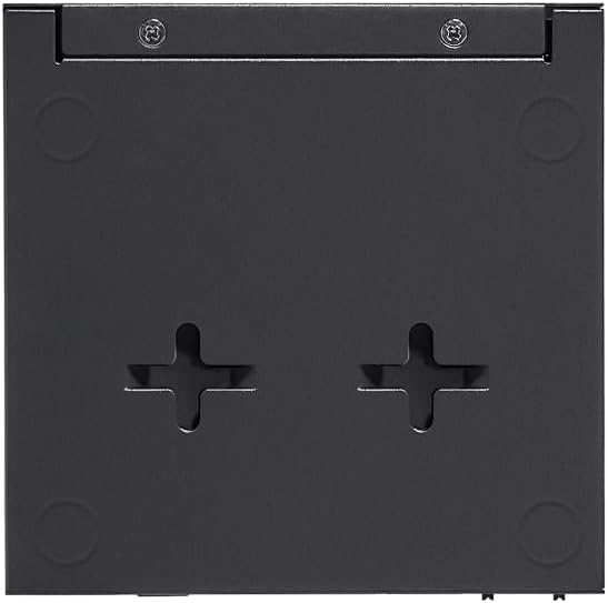
Image 3: Bottom view of the TP-Link Omada ES205GP switch, showing mounting holes for wall installation and areas for rubber feet.
- Mounting Holes: For wall-mounting the device.
- Rubber Feet Slots: For attaching the included rubber feet for desktop placement.
4. Setup
4.1 Physical Installation
The ES205GP switch can be placed on a desktop or mounted on a wall.
Desktop Placement:
Attach the included rubber feet to the recessed areas on the bottom of the switch. Place the switch on a flat, stable surface, ensuring adequate ventilation around the device.
Wall Mounting:
Use the provided wall mounting kit. Mark two positions on the wall, ensuring they align with the mounting holes on the bottom of the switch. Drill pilot holes, insert anchors, and then screw in the mounting screws, leaving a small gap. Align the switch's mounting holes with the screws and slide the switch down to secure it.
4.2 Connecting Devices
- Connect to Power: Plug the power adapter into the switch's power input and then into a power outlet. The Power LED should illuminate green.
- Connect Network Devices:
- For non-PoE devices (e.g., router, PC, NVR), connect an Ethernet cable from the device to any of the RJ45 ports (1-5).
- For PoE-powered devices (e.g., IP cameras, access points, VoIP phones), connect an Ethernet cable from the device to one of the PoE+ ports (1-4). Ensure the device is 802.3af/at compliant.
- Verify Connections: Check the Link/Activity LEDs on the connected ports. A solid green or yellow light indicates a successful link, and blinking indicates data transmission.
Note: The total PoE power budget for the ES205GP is 65W, with up to 30W available per port. Ensure the total power consumption of all connected PoE devices does not exceed 65W.
5. Operating the Switch
5.1 LED Indicators
| LED | Status | Indication |
|---|---|---|
| Power | Green | Switch is powered on. |
| PoE Max | Green | Total PoE power consumption is less than 65W. |
| PoE Max | Flashing Green | Total PoE power consumption is between 65W and 70W. |
| PoE Max | Yellow | Total PoE power consumption exceeds 70W. PoE power to lower priority ports may be cut off. |
| Link/Activity (per port) | Green | 1000Mbps link established. |
| Link/Activity (per port) | Yellow | 10/100Mbps link established. |
| Link/Activity (per port) | Blinking | Data is being transmitted or received. |
5.2 Centralized Cloud Management
The ES205GP switch can be managed centrally via the Omada SDN platform. This allows for remote configuration and monitoring through a web browser or the Omada app.
- Accessing the Omada Controller: If you have an existing Omada Controller (hardware, software, or cloud-based), the switch can be adopted into your network. Refer to your Omada Controller's documentation for adoption procedures.
- Omada App: Download the TP-Link Omada app from your mobile device's app store. Follow the in-app instructions to add and manage your Omada devices.
- Web Interface: For direct management, connect a computer to the switch and access its web-based management interface. The default IP address and login credentials can be found in the Quick Installation Guide or on the TP-Link support website.
Note: For detailed configuration options and advanced features like VLAN, QoS, and Loop Prevention, refer to the comprehensive Omada SDN Controller User Guide available on the TP-Link website.
6. Maintenance
6.1 Firmware Updates
Regularly check the TP-Link official website for the latest firmware updates for your ES205GP switch. Firmware updates can improve performance, add new features, and fix bugs. Follow the instructions provided with the firmware download carefully.
6.2 Cleaning
To clean the switch, disconnect it from power and use a soft, dry cloth. Do not use liquid or aerosol cleaners. Ensure no dust accumulates in the ventilation holes.
6.3 Resetting to Factory Defaults
If the switch is not functioning correctly or you need to clear all configurations, you can reset it to factory default settings. With the switch powered on, use a paperclip or similar pointed object to press and hold the Reset button on the rear panel for approximately 5 seconds. Release the button when the LEDs flash, indicating the reset process has begun.
7. Troubleshooting
7.1 No Power
- Ensure the power adapter is securely connected to the switch and a working power outlet.
- Verify the power outlet is functional by plugging in another device.
- Check the power adapter for any visible damage.
7.2 No Link on a Port
- Check the Ethernet cable connection at both ends. Try a different cable.
- Ensure the connected device is powered on and functioning correctly.
- Try connecting to a different port on the switch.
7.3 PoE Device Not Receiving Power
- Ensure the device is connected to one of the PoE+ ports (1-4).
- Verify the connected device is 802.3af/at compliant.
- Check the PoE Max LED. If it's yellow, the total power budget may be exceeded. Disconnect some PoE devices or replace them with lower-power alternatives.
- Try a different Ethernet cable.
- Ensure the cable length does not exceed 100 meters (standard Ethernet limit). For extended distances up to 250m, ensure the switch is configured for "Extend Mode" via the Omada Controller, if available.
For further assistance, refer to the TP-Link support website or contact technical support.
8. Specifications
| Feature | Detail |
|---|---|
| Model | ES205GP |
| Ports | 5x 10/100/1000Mbps RJ45 Ports (4x 802.3af/at PoE+) |
| PoE+ Standard | 802.3af/at compliant |
| PoE Power Budget | 65W total, up to 30W per port |
| Data Transfer Rate | 5000 Megabits Per Second (5 Gbps switching capacity) |
| Management | Easy Smart Managed (Omada SDN, Web UI, Omada App) |
| Features | QoS, VLAN, PoE Auto Recovery, Loop Prevention, Port Isolation, Fanless Design |
| Case Material | Metal |
| Dimensions | 7.72 x 5.2 x 4.72 inches (Package) |
| Item Weight | 1.63 pounds |
| UPC | 810142820431 |
9. Warranty Information
TP-Link products come with a limited warranty. For detailed warranty terms and conditions, please visit the official TP-Link website and navigate to the support section for your region. Keep your purchase receipt as proof of purchase for warranty claims.
10. Technical Support
For technical support, firmware updates, and frequently asked questions, please visit the TP-Link support website:
You can also find contact information for your regional support team on the website.