
1. Introduction
This manual provides detailed instructions for the installation, operation, and maintenance of the Poynting EPNT-2 antenna enclosure. The EPNT-2 is designed to integrate a 4G/5G router within its robust enclosure, creating a comprehensive Customer Premises Equipment (CPE) solution. It features cross-polarised, high-gain cellular antennas and omni-directional Wi-Fi antennas, suitable for a wide range of wireless communication applications.
2. Product Overview
The Poynting EPNT-2 is an advanced antenna enclosure system incorporating both cellular and Wi-Fi antenna elements. It utilizes Artificial Magnetic Conductor (AMC) technology for enhanced performance. The enclosure is designed to accommodate various router modules, transforming into a complete CPE unit. Its robust construction ensures durability in diverse environmental conditions.
- Cellular Frequency Coverage: 617 – 960 MHz, 1710 – 2700 MHz, 3400 – 4200 MHz.
- Wi-Fi Frequency Coverage: 2400 – 2500 MHz, 5000 – 7200 MHz.
- Cellular Antenna Configuration: Four cross-polarised antennas, including two uni-directional (up to 11 dBi peak gain) and two omni-directional (up to 5 dBi peak gain), supporting 4x4 MIMO or dual 2x2 MIMO routers.
- Wi-Fi Antenna Configuration: Two omni-directional dual-band Wi-Fi antennas for 2x2 MIMO.
- Router Accommodation: Designed for routers up to 185 x 145 x 45 mm³.
- Environmental Rating: IP65 weatherproof and waterproof.

Figure 1: Front view of the Poynting EPNT-2 antenna enclosure, showcasing its compact and durable design.
3. Safety Information
Please read and understand all safety instructions before installing or operating the EPNT-2 antenna. Failure to do so may result in injury or damage to the equipment.
- General Safety: Ensure all power sources are disconnected before installation or maintenance.
- Mounting: Mount the antenna securely to a stable structure capable of supporting its weight and resisting wind loads.
- Lightning Protection: Consider appropriate lightning protection measures for outdoor installations.
- RF Exposure: Maintain a safe distance from the antenna during operation to minimize exposure to radio frequency (RF) energy. Consult local regulations for specific guidelines.
- Cabling: Use appropriate outdoor-rated cables and connectors to maintain the IP65 rating.
4. Setup and Installation
Proper installation is crucial for optimal performance and longevity of the EPNT-2 antenna. Follow these steps carefully.
4.1. Package Contents
Verify that all components are present before beginning installation. (Note: Specific package contents are not detailed in the provided product information. Typically includes the antenna unit, mounting hardware, and possibly a quick start guide.)
4.2. Router Integration
- Open the Enclosure: Carefully remove the cover of the EPNT-2 enclosure. Refer to Figure 4 for guidance.
- Insert Router: Place your compatible 4G/5G router into the designated space within the enclosure. Ensure it fits within the maximum dimensions of 185 x 145 x 45 mm³. Refer to Figure 3 for an example of a router installed.
- Connect Cables: Connect the internal antenna cables from the EPNT-2 to the corresponding cellular and Wi-Fi ports on your router. Ensure secure connections.
- Secure Router: Use any provided internal mounting mechanisms or straps to secure the router firmly within the enclosure.
- Close Enclosure: Carefully re-attach the cover, ensuring a tight seal to maintain the IP65 rating.

Figure 3: Internal view of the EPNT-2 enclosure showing a router installed and connected to the internal antenna cables.

Figure 4: Exploded view illustrating the removal of the EPNT-2 enclosure cover for router installation.
4.3. Mounting the Antenna
The EPNT-2 is designed for various mounting options. The back of the unit features integrated mounting brackets.
- Select Location: Choose a mounting location that provides a clear line of sight to cellular towers and Wi-Fi access points, free from obstructions.
- Secure Brackets: Attach the appropriate mounting hardware (not explicitly detailed, but typically pole or wall mounts) to the desired surface.
- Mount Antenna: Secure the EPNT-2 antenna to the mounting hardware using the integrated brackets on the back of the unit. Ensure it is firmly attached and oriented correctly for optimal signal reception.
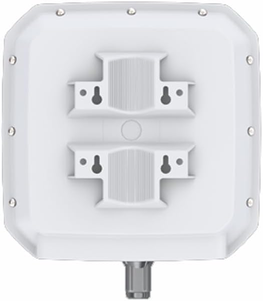
Figure 2: Rear view of the Poynting EPNT-2, showing the integrated mounting brackets for secure installation.
4.4. Cable Connections
After mounting and router integration, connect external cables.
- Power: Connect the power supply to your integrated router as per its instructions.
- Ethernet: If applicable, connect an Ethernet cable from the router's LAN port to your network infrastructure. Ensure any external cable glands are properly sealed.
5. Operating Instructions
Once the EPNT-2 with the integrated router is installed and powered, its operation is primarily managed through the router's interface. The antenna itself is a passive component designed to enhance signal reception and transmission.
- Power On: Ensure the integrated router receives power.
- Router Configuration: Access your router's web interface or management application to configure cellular and Wi-Fi settings.
- Signal Monitoring: Monitor signal strength indicators on your router to verify optimal antenna orientation and performance. Adjust antenna position slightly if necessary to maximize signal.
6. Maintenance
The EPNT-2 antenna is designed for minimal maintenance due to its robust construction and IP65 rating.
- Periodic Inspection: Periodically inspect the antenna and mounting hardware for any signs of wear, damage, or loose connections.
- Cleaning: Clean the exterior of the enclosure with a soft, damp cloth if dirt or debris accumulates. Avoid abrasive cleaners or solvents.
- Seal Integrity: Ensure all cable glands and the enclosure seal remain intact to prevent water ingress.
7. Troubleshooting
If you experience issues with your EPNT-2 antenna system, consider the following troubleshooting steps:
- No Signal/Poor Signal:
- Verify antenna orientation towards cellular towers.
- Check all cable connections for tightness and proper seating.
- Ensure the integrated router is powered on and configured correctly.
- Inspect cables for damage.
- Confirm SIM card (if applicable) is correctly inserted and active in the router.
- Intermittent Connectivity:
- Check for potential sources of interference (e.g., other electronic devices, large metal objects).
- Ensure the antenna is securely mounted and not subject to movement.
- Verify router firmware is up to date.
- Water Ingress:
- Immediately disconnect power.
- Inspect the enclosure seal and cable glands for damage or improper sealing.
- Contact support if damage is found.
For further assistance, refer to your router's manual or contact Poynting support.
8. Specifications
Detailed technical specifications for the Poynting EPNT-2 antenna.
| Feature | Specification |
|---|---|
| Model | EPNT-2 |
| Brand | Poynting |
| Cellular Frequency Bands | 617 – 960 MHz, 1710 – 2700 MHz, 3400 – 4200 MHz |
| Wi-Fi Frequency Bands | 2400 – 2500 MHz, 5000 – 7200 MHz |
| Cellular Peak Gain (617-960 MHz) | 9 dBi |
| Cellular Peak Gain (1710-2700 MHz) | 8.5 dBi |
| Cellular Peak Gain (3400-4200 MHz) | 11 dBi |
| Wi-Fi Peak Gain (2400-2500 MHz) | 3 dBi |
| Wi-Fi Peak Gain (5000-7200 MHz) | 7 dBi |
| Impedance | 50 Ohm |
| Router Accommodation Size | Up to 185 x 145 x 45 mm³ |
| Ingress Protection (IP) Rating | IP65 |
| Color | White |
| Manufacturer | Poynting |
9. Warranty and Support
Poynting products are designed for reliability and performance. For warranty information, please refer to the documentation provided with your purchase or visit the official Poynting website. For technical support, contact Poynting customer service through their official channels.
Manufacturer: Poynting
Date First Available: June 19, 2023


