Introduction
The M5Stack Core2 ESP32 IoT Development Kit V1.1 is a versatile, open-source development platform designed for Internet of Things (IoT) projects. It integrates a powerful ESP32-D0WDQ6-V3 dual-core processor, a 2.0-inch capacitive touchscreen, and a suite of integrated sensors and peripherals. This manual provides essential information for setting up, operating, and maintaining your Core2 V1.1 device.
What's in the Box
Upon opening the package, verify that all the following items are included:
- 1x Core2 V1.1 device
- 1x USB Type-C cable (20cm)
- 1x HEX KEY

Image: Contents of the M5Stack Core2 V1.1 package, including the main device, a USB Type-C cable, and a hex key.
Product Overview
The M5Stack Core2 V1.1 is built around the ESP32-D0WDQ6-V3 chip, featuring dual Xtensa 32-bit LX6 processors operating at up to 240MHz. This provides robust performance for complex applications. The device includes a 2.0-inch capacitive touchscreen with three virtual touch buttons for interactive user experiences.
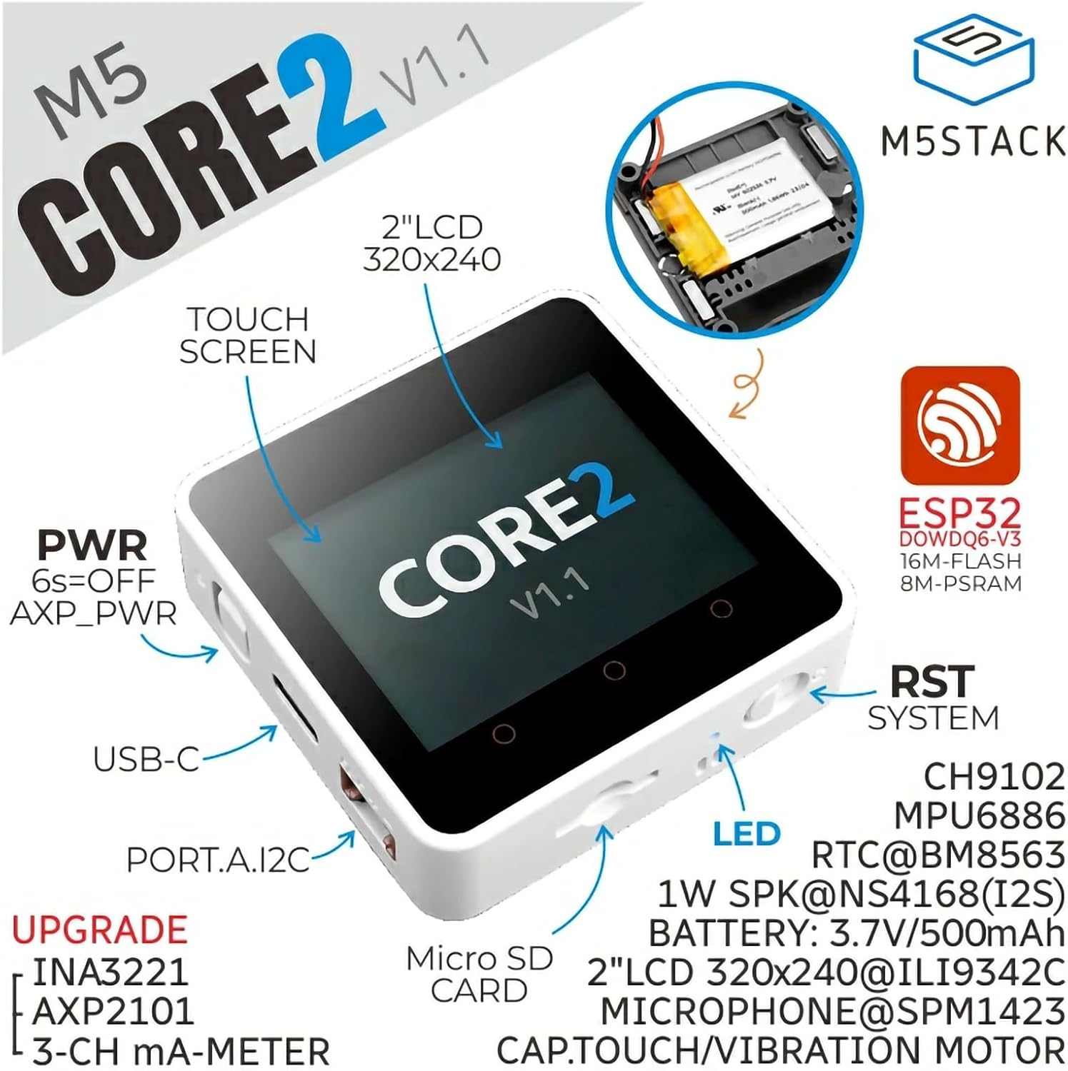
Image: Front view of the M5Stack Core2 V1.1, illustrating key features such as the 2-inch LCD, capacitive touchscreen, USB-C port, power button, Micro SD card slot, LED indicator, and system reset button.
Enhanced power management is provided by the AXP2101 chip and INA3221 current meter, improving energy efficiency and enabling accurate power monitoring. Connectivity options include built-in Wi-Fi and a Type-C interface for program downloading. A MicroSD card slot supports up to 16GB of storage for various IoT projects.
Image: Side view of the M5Stack Core2 V1.1, detailing the power button, USB-C port, and Port.A I2C connector for external modules.
The device also integrates a 6-axis IMU sensor, a speaker, a vibration motor, and a PDM microphone, offering comprehensive functionality for interactive and sensory applications. Its compact design measures 2.13 x 2.13 x 0.65 inches and weighs approximately 2.89 ounces.

Image: Dimensions of the M5Stack Core2 V1.1, indicating its compact size.

Image: M5Stack Core2 V1.1 on a digital scale, showing its net weight.
The Core2 V1.1 supports multiple development platforms, including UIFlow and Arduino, providing flexibility for developers.

Image: M5Stack Core2 V1.1 demonstrating compatibility with UIFlow and Arduino development environments.
Setup
- Initial Charge: Connect the Core2 V1.1 to a power source using the provided USB Type-C cable. Ensure the device is fully charged before first use.
- Power On: Press and hold the power button (labeled "PWR" on the side) for approximately 6 seconds to power on the device.
- Software Setup: To begin development, you will need to install the appropriate development environment (e.g., Arduino IDE with M5Stack libraries or UIFlow). Refer to the official M5Stack documentation for detailed installation instructions.
- MicroSD Card Insertion: If using a MicroSD card for storage, gently insert it into the MicroSD card slot on the side of the device until it clicks into place.
Image: M5Stack Core2 V1.1 highlighting the USB-C port for charging and data transfer, and the Micro SD card slot.
For detailed tutorials and development guides, visit the official M5Stack website. The following image illustrates how to access these resources:

Image: Steps to find tutorials on the M5Stack website.
Operating Instructions
The Core2 V1.1 features a capacitive touchscreen for interaction. The default firmware often includes a test program that demonstrates various functionalities such as Wi-Fi scanning, timer functions, and sensor readings.

Image: The Core2 V1.1 display showing a system test interface, demonstrating various functions.
To explore the device's capabilities and learn how to program it, refer to the official M5Stack documentation and examples. The embedded video below provides a visual overview of the device's features and basic operation:
Video: An official M5Stack video demonstrating the unboxing, features, and basic operational tests of the Core2 ESP32 IoT Development Kit V1.1, including touchscreen interaction, Wi-Fi scanning, and sensor feedback.
Specifications
Key technical specifications for the M5Stack Core2 ESP32 IoT Development Kit V1.1:
| Feature | Parameter |
|---|---|
| Processor | ESP32-D0WDQ6-V3 (240 MHz, Dual-Core) |
| Flash Memory | 16MB |
| PSRAM | 8MB |
| Input Voltage | 5V @ 500mA |
| Host Interface | Type-C x 1, GROVE (I2C+I/O+UART) x 1 |
| LED | Blue power indicator light |
| Buttons | Power button, RST button, 3 virtual screen buttons |
| Vibration Alert | Vibration motor |
| Wireless Type | 802.11n (Wi-Fi) |
| Operating System | Linux (underlying OS for ESP32) |
| Item Weight | 2.89 ounces (approx. 82g) |
| Product Dimensions | 2.13 x 2.13 x 0.65 inches (54 x 54 x 16.5 mm) |

Image: Detailed specifications table for the M5Stack Core2 V1.1.
Maintenance
- Cleaning: Use a soft, dry cloth to clean the device. Avoid using liquid cleaners or solvents, as they may damage the screen or internal components.
- Storage: Store the Core2 V1.1 in a cool, dry place away from direct sunlight and extreme temperatures.
- Battery Care: To prolong battery life, avoid fully discharging the device frequently. If storing for extended periods, charge the battery to approximately 50% and recharge every few months.
- Firmware Updates: Regularly check the official M5Stack website for firmware updates to ensure optimal performance and access to new features.
Troubleshooting
- Q: How to connect an extension module?
- A: You must remove the original bottom casing and battery of the Core2 V1.1 to stack another module extension.
- Q: The memory card fails to read.
- A: You can add specific code during initialization to enhance the host's memory card reading capability. For example, in Arduino, you might use:
for (auto gpio: (const uint8_t[]){18, 19, 23}) (*(volatile uint32_t*)GPIO_PIN_MUX_REG[gpio]) |= FUN_DRV_M; gpio_pulldown_dis((gpio_num_t)gpio); gpio_pullup_en((gpio_num_t)gpio);}This code snippet is intended for advanced users familiar with ESP32 GPIO configuration.

Image: Frequently Asked Questions (FAQ) section from M5Stack, addressing common issues.
Warranty and Support
For warranty information, technical support, and additional resources, please visit the official M5Stack website or contact their customer service. Keep your purchase receipt for warranty claims.
Official M5Stack Website: www.m5stack.com


