Introduction
This manual provides comprehensive instructions for the assembly, operation, and maintenance of the GODIYMODULES 6-Bit Digital Electronic Alarm Clock Kit. This kit is designed to help users learn fundamental mechanical and electronic skills, including soldering, circuit understanding, and digital display operation. It features a 6-bit digital display and is based on the AT89C2051 microcontroller.
Product Overview
The kit includes all necessary components to build a functional 6-bit digital electronic clock with alarm capabilities. Key components include the AT89C2051 microcontroller, FR-4 PCB, 7-segment digital displays, resistors, capacitors, transistors, and a buzzer.
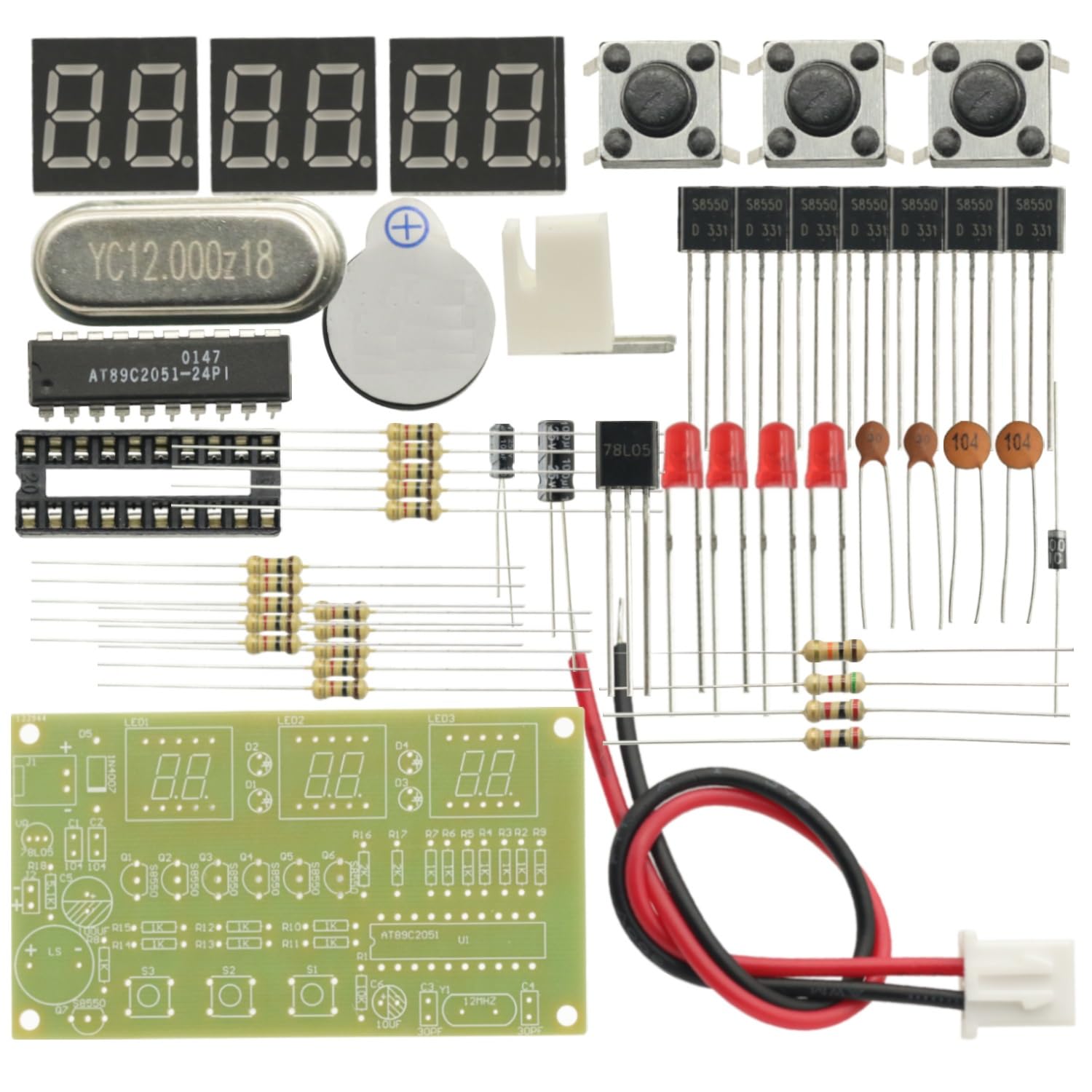
Image: All components of the GODIYMODULES 6-Bit Digital Electronic Alarm Clock Kit.
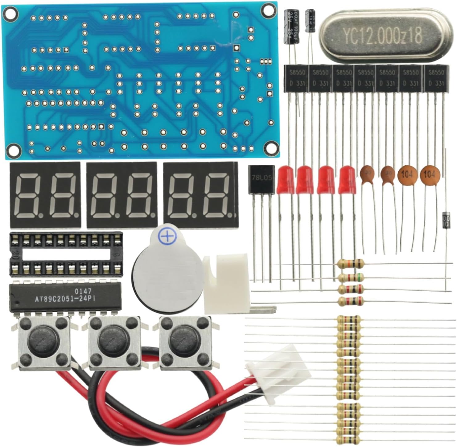
Image: A closer view of the kit's components, showing the PCB, digital displays, and other electronic parts.
Setup and Assembly
Assembly of this kit requires soldering. Follow these general guidelines for successful construction:
- Component Placement: Align all components with the PCB silkscreen markings. Pay attention to the orientation of polarized components such as diodes, electrolytic capacitors, and integrated circuits (ICs).
- Soldering Sequence: Solder components from lowest to highest profile. Start with resistors and diodes, then move to taller components like capacitors and IC sockets.
- Polarized Components: Ensure the longer lead (positive) aligns with the '+' marking on the PCB. Incorrect orientation can damage components.
- IC Orientation: Align the semicircular notch on the IC with the corresponding notch on the PCB silkscreen.
- Resistors/Capacitors: Verify values with a multimeter or by matching color codes before soldering.
- Soldering Temperature: Maintain a soldering iron tip temperature between 320°C-380°C (608°F-716°F). Avoid prolonged heating (max 3-5 seconds per joint) to prevent PCB or component damage.
- Power Labels: Connect power correctly to the 'VCC' and 'GND' terminals.

Image: Top view of the FR-4 Printed Circuit Board (PCB) with component outlines for assembly.

Image: Bottom view of the FR-4 PCB, illustrating the solder pads and circuit traces.
Video: Demonstration of a 6-bit digital LED electronic clock DIY kit, showing its functionality and button presses.
Video: Assembly and operation of a DC 4.5V-5.5V 6-bit digital circuit clock kit.
Video: A soldering practice kit for a DIY digital clock electronics project, showing unboxing and assembly steps.
Video: Assembly and demonstration of a Gikfun 4-bit digital LED soldering clock DIY kit.
Video: Overview of recommended LED clock soldering practice DIY kits, showcasing various models.
Operating Instructions
The clock kit offers various functions including time display, time setting, alarm setting, countdown timer, stopwatch, counter, and hourly chime. The operation is primarily controlled via the onboard buttons (S1, S2, S3).
Operation Principle:
- Single-chip Circuit: The core of the clock is the AT89C2051 microcontroller, which manages all timing and control functions, including power-on reset and clock circuit.
- Display Circuit: The clock utilizes 6-bit digital tube displays (red). PNP transistors drive the segments, with current-limiting resistors at each port. The display uses a scanning-driven method, primarily via pins P1.0-P1.6. The colon indicators use four Φ3 red diodes, also scanning-driven via pin P1.7.
- Keyboard Input: Buttons S1, S2, and S3 are multi-functional and share pins P3.5, P3.4, and P3.2 with the display. Pressing a button outputs a high level at the corresponding pin, which the microcontroller reads and debounces to register the input.
- Signal Ringing Circuit: A buzzer and PNP transistor form the alarm circuit. When activated, the PNP transistor turns on, causing the buzzer to emit sound at a fixed frequency. This circuit uses an independent port-driven method via pin P3.7. Connector J1 allows for external control equipment, outputting a low level when no ringing signal is present and a high level during a ringing signal.
- Power Circuit: A three-terminal integrated circuit provides stable voltage to the entire system.
Setting the Time and Other Functions:
Specific button presses (short press, long press, combinations) will navigate through modes and adjust values. Refer to the included quick setup guide for detailed button functions for setting time, alarm, countdown, and other features.
Video: Demonstration of a 4-bit digital clock soldering practice kit, showing how to set the time and adjust brightness.
Maintenance
To ensure the longevity and proper functioning of your digital clock kit, consider the following maintenance tips:
- Cleaning: Keep the PCB and components free from dust and debris. Use a soft, dry brush or compressed air for cleaning. Avoid using liquids directly on the circuit board.
- Power Supply: Always use a stable DC 7-12V power supply. Incorrect voltage can damage the components.
- Soldering Joints: Periodically inspect soldering joints for any signs of cold joints, cracks, or corrosion. Re-solder if necessary.
- Component Replacement: If a component fails, ensure you replace it with an identical or equivalent part to maintain circuit integrity.
Troubleshooting
If you encounter issues with your assembled clock kit, refer to the following common troubleshooting steps:
- No Power/Display:
- Verify the power supply is connected correctly and providing the specified DC 7-12V.
- Check for any short circuits or loose connections on the PCB.
- Ensure all polarized components (diodes, electrolytic capacitors, ICs) are oriented correctly.
- Incorrect Time/Functionality:
- Confirm the AT89C2051 chip is seated correctly in its socket.
- Check the crystal oscillator (12MHz) for proper soldering and functionality.
- Inspect the buttons (S1-S3) for proper operation and connectivity.
- Display Issues (e.g., missing segments, dimness):
- Check the soldering of the 7-segment displays and their current-limiting resistors.
- Ensure the PNP transistors driving the display segments are correctly installed and functioning.
- Alarm Not Sounding:
- Verify the buzzer and its associated PNP transistor are correctly installed and soldered.
- Check the alarm settings to ensure it is enabled and set to the desired time.
Specifications
| Feature | Detail |
|---|---|
| Brand | GODIYMODULES |
| Model | C51 AT89C2051 Digital Clock Kit |
| Operating Voltage | DC 7-12V |
| Microcontroller | AT89C2051 |
| PCB Size | 7" x 2" (92 x 49mm) |
| Display Type | 6-Bit Digital (Red) |
| Functions | Clock, Time Set, Alarm Set, Countdown Timer, Stopwatch, Counter, Hourly Chime, 24-hour format |
| Time Accuracy | ±1 second per 24 hours |
| Item Weight | 0.704 ounces |
| Package Dimensions | 3.94 x 1.97 x 0.39 inches |
Warranty and Support
This DIY kit is intended for educational and hobbyist purposes. Due to the nature of DIY assembly, specific warranties on individual components may vary. Please refer to the retailer's return policy for details on defective or missing parts upon receipt.
For technical support or inquiries regarding assembly, please contact the manufacturer or retailer through their official channels. Online resources, forums, and community groups dedicated to electronics DIY kits can also provide valuable assistance.


