1. Introduction
This manual provides essential instructions for the proper installation, operation, and maintenance of your SPARKHOBBY 5.8G 2.0W VTX. Please read this manual thoroughly before use to ensure optimal performance and safety.
Important Safety Warning: Please ensure to connect the antenna before powering on the VTX. Failure to do so will result in permanent damage to the unit.
2. Product Features
- 64 working channels with button selection settings.
- 4 power levels with button selection settings.
- 5.8GHz video transmission transmitter, compatible with PAL and NTSC video formats.
- Compact structure, small size, and high transmission power.
- Utilizes large-scale integrated circuits and automotive-grade components for high reliability.
- Built-in frequency phase-locked loop for low harmonic radiation, high reliability, and stability using a digital phase-locked loop circuit, eliminating temperature drift.
- Supports TBS protocol OSD parameter tuning.
3. Specifications
| Parameter | Value |
|---|---|
| Weight (excluding antenna) | 13.5g |
| Dimensions (L*W*T) | 36 * 36 * 10mm |
| Fixed Hole Spacing | 30.5 * 30.5mm |
| Working Voltage | DC 7V-36V (2S-8S) |
| Working Current (at 12V) | 600mA ± 100mA |
| Maximum Power Consumption | 7W |
| RF Transmission Power | > 33dBm (2.0W) |
4. Component Identification and Interface Definition

Figure 4.1: Top view of the VTX module, highlighting control buttons and LED indicators.
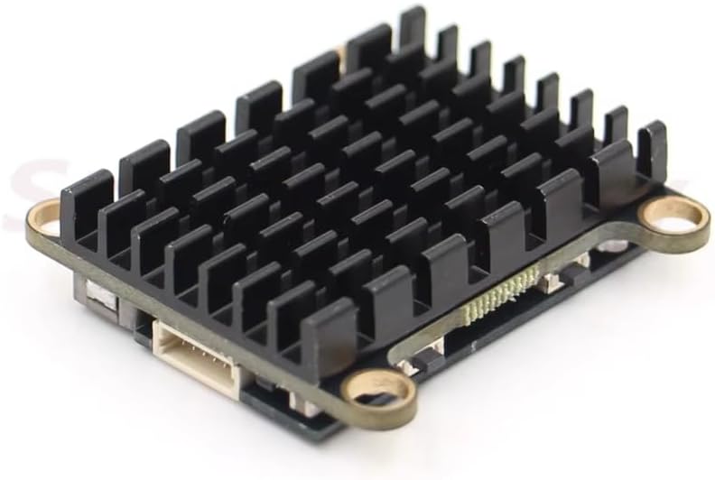
Figure 4.2: Side view of the VTX, illustrating the integrated heatsink for thermal management.

Figure 4.3: Outline dimension diagram showing the 30.5 x 30.5mm mounting hole pattern.
4.1 Interface Pinout
- Red thick line DC-IN: Image transmission power input positive pole, supporting a range of 7-36V.
- Black thick line GND: Represents the negative input of the power supply.
- Yellow Video: Analog Video Signal input.
- White Data OSD: OSD tuning communication data cable, supporting the TBS protocol.
- Black thin line GDN: Image transmission output negative electrode.
- Red thin line 5V-OUT: Image transmission output positive pole, maximum output current 350mA. Attention: Connecting a wide voltage camera (e.g., 5-12V) to this output may result in insufficient power supply voltage and no image if the camera draws too much current.
5. Setup and Connection
Follow these steps to correctly connect your SPARKHOBBY 5.8G 2.0W VTX:
- Antenna Connection: Before applying power, securely connect a 5.8GHz antenna to the VTX's antenna port. Failure to do so will permanently damage the VTX.
- Power Connection: Connect the red thick wire (DC-IN) to the positive terminal of your power source (7V-36V DC) and the black thick wire (GND) to the negative terminal.
- Video Input: Connect your FPV camera's video output to the yellow "Video" wire on the VTX.
- OSD Data (Optional): If using OSD parameter tuning via TBS protocol, connect the white "Data OSD" wire to the appropriate data pin on your flight controller.
- 5V Output (Optional): The red thin wire (5V-OUT) provides a 5V output (max 350mA) for powering low-current devices like a camera. Ensure the connected device's current draw does not exceed 350mA.

Figure 5.1: The VTX module with its wiring harness and an example antenna, illustrating typical components for connection.
6. Operating Instructions
The VTX features two buttons for adjusting frequency (channel) and power levels.
6.1 Channel and Band Selection
Use the KEY-FREQ button to cycle through the available channels and bands. The LED-CH indicator will display the current channel/band. Refer to the frequency table below for specific values.
6.2 Power Level Adjustment
Use the KEY-PWR/BAND button to cycle through the 4 available power levels. The LED-PWR/BAND indicator will show the selected power level.

Figure 6.1: VTX control interface and frequency/power table (original diagram, refer to translated instructions for details).
6.3 OSD Parameter Tuning (TBS Protocol)
The VTX supports OSD parameter tuning via the TBS protocol. Connect the "White Data OSD" wire to your flight controller and configure your OSD software (e.g., Betaflight, ArduPilot) to utilize the TBS SmartAudio or similar protocol for VTX control. This allows for convenient adjustment of channels, bands, and power levels directly from your FPV goggles or ground station OSD.
7. Troubleshooting
- No Video Signal:
- Ensure the antenna is securely connected before powering on.
- Verify power connections (DC-IN and GND) are correct and within the 7V-36V range.
- Check the video input connection from the camera to the VTX.
- If using the 5V-OUT for the camera, ensure the camera's current draw does not exceed 350mA. Insufficient current can lead to no image.
- Confirm that your FPV receiver is on the correct frequency and band as the VTX.
- Poor Video Quality/Range:
- Check for obstructions between the VTX and receiver antenna.
- Ensure both VTX and receiver antennas are correctly oriented and compatible.
- Increase the VTX power level (if legally permitted in your region).
- Inspect antennas for damage.
- VTX Overheating:
- Ensure adequate airflow around the VTX, especially when operating at higher power levels.
- Verify the VTX is not enclosed in a way that prevents heat dissipation.
- Operating without an antenna will cause immediate and severe overheating, leading to damage.
8. Maintenance
- Keep the VTX clean and free from dust and debris.
- Avoid exposing the VTX to moisture or extreme temperatures.
- Regularly inspect all connections for wear or damage.
- Ensure the heatsink remains clear for effective cooling.
9. Warranty and Support
SPARKHOBBY products are manufactured to high-quality standards. For warranty information or technical support, please refer to the official SPARKHOBBY website or contact your retailer. Please retain your proof of purchase for warranty claims.
For further assistance, visit the SPARKHOBBY Store on Amazon.


